A hand-push small pruning machine for pruning shrubs
A hand-push and pruning machine technology, which is applied in applications, electric pruning saws, agricultural machinery and equipment, etc., can solve the problems of high work intensity of pruning personnel, affecting the appearance of the road, and obstruction of passing pedestrians, so as to improve pruning efficiency, The effect of beautiful environment and increasing diversity
- Summary
- Abstract
- Description
- Claims
- Application Information
AI Technical Summary
Problems solved by technology
Method used
Image

Examples
Embodiment 1
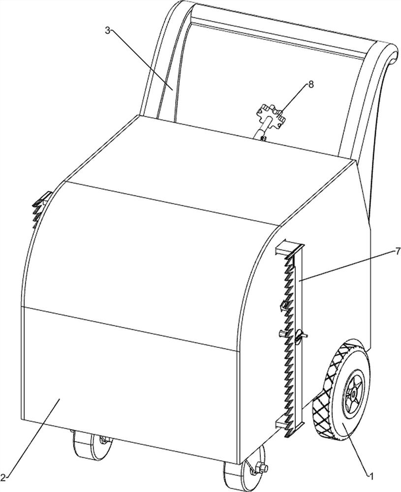
[0023] A small hand-push trimmer for shrub trimming, such as Figure 1-3 As shown, it includes a chassis 1, a shell 2, a handle 3, a frame 4, a placing frame 5, a transmission assembly 6 and a trimming assembly 7. The top of the chassis 1 is connected with the shell 2, and the upper rear side of the shell 2 is connected There is a push handle 3, a frame 4 is connected to the front side of the top of the underframe 1, a placement frame 5 is connected to the top and rear of the underframe 1, and a transmission assembly 6 is installed between the top of the placement frame 5 and the middle of the frame 4. A trimming assembly 7 is installed between the left and right sides of the frame 4 .
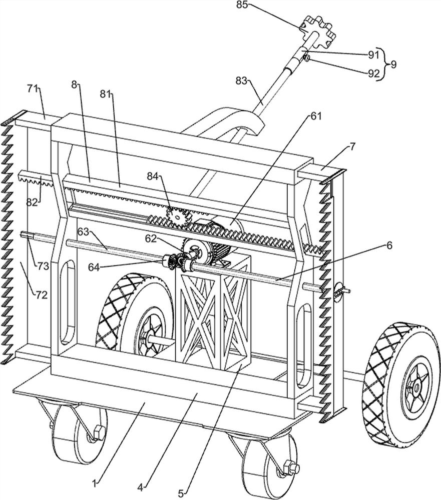
[0024] The transmission assembly 6 includes a motor 61, a driving bevel gear 62, an inner hexagonal drum 63 and a transmission bevel gear 64. A motor 61 is installed on the top of the placing frame 5, and the output shaft of the motor 61 is connected with a driving bevel gear 62. The rack 4 T...
Embodiment 2
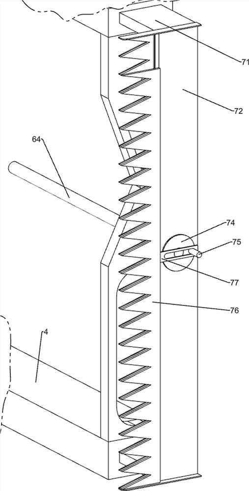
[0028] On the basis of Example 1, as figure 2 As shown, it also includes an adjustment assembly 8. The adjustment assembly 8 includes a guide plate 81, an adjustment rack 82, a connecting rod 83, an adjustment gear 84 and a torsion plate 85. The middle of the frame 4 is connected with two upper and lower guide plates 81. Above the inner hexagonal drum 63 , an adjusting rack 82 is slidably connected to the guide plate 81 , one end of the adjusting rack 82 is connected to the first saw blade 72 , and the top of the rear end of the frame 4 is rotatably connected to a connecting rack 82 . The rod 83, the front end of the connecting rod 83 is connected with an adjusting gear 84, and the adjusting gear 84 meshes with the two adjusting racks 82. The tail end of the connecting rod 83 passes through the housing 2 and is connected with a torsion plate 85.
[0029] When the road is too wide to be trimmed at the same time, manually rotate the torsion plate 85 to drive the adjustment gear...
PUM
 Abstract
Description
Claims
Application Information
 - R&D
- Intellectual Property
- Life Sciences
- Materials
- Tech Scout
- Unparalleled Data Quality
- Higher Quality Content
- 60% Fewer Hallucinations
Browse by: Latest US Patents, China's latest patents, Technical Efficacy Thesaurus, Application Domain, Technology Topic, Popular Technical Reports.
© 2025 PatSnap. All rights reserved.Legal|Privacy policy|Modern Slavery Act Transparency Statement|Sitemap|About US| Contact US: help@patsnap.com