Traction reduction device for osteosynthesis for tibia fracture
A traction reduction and tibial technology, which is applied in the field of traction reduction devices for tibial fracture and osteosynthesis surgery, can solve the problems of large space occupation, poor traction stability, and low adjustment accuracy
- Summary
- Abstract
- Description
- Claims
- Application Information
AI Technical Summary
Problems solved by technology
Method used
Image
Examples
Embodiment 1
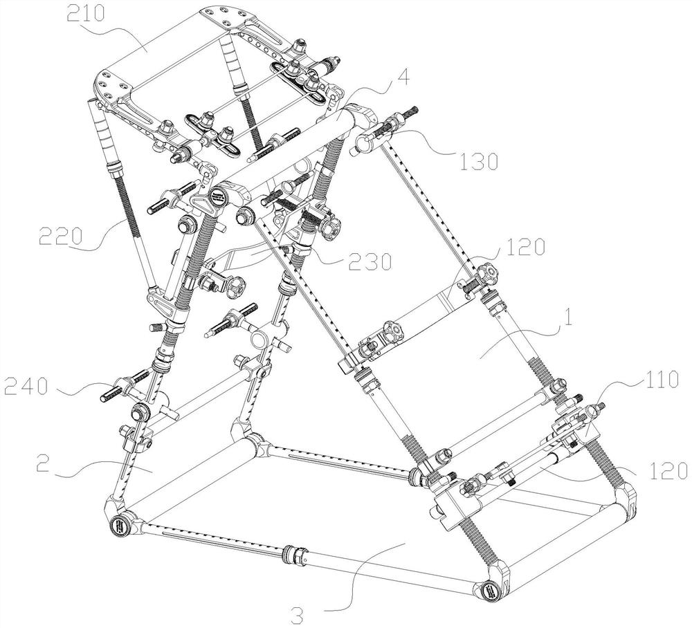
[0101] like Figure 1 to Figure 16 As shown, an embodiment of the distraction reduction device for tibial fracture osteosynthesis of the present disclosure includes a support frame and a tibial distraction mechanism 110 .
[0102] The support frame is placed on the operating table, which is surrounded by three faces to form a triangular structure, the support frame has a calf support surface 1 for carrying the patient's calf, and a support portion 4 for supporting the patient's knee joint is formed on the top. , used to support the patient's lower extremity to form and maintain a bent leg.
[0103] The tibial traction mechanism 110 is arranged on the calf bearing surface 1, and is used for pulling the Kirschner wire passing through the patient's ankle bone or the distal end of the tibia to promote the effective reduction of the broken tibia bone.
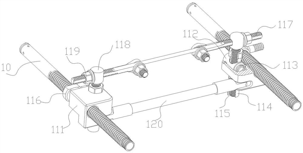
[0104] like figure 2 As shown, the tibial distraction mechanism 110 includes two sliders one 111 , two quick adjusting blocks o...
Embodiment 2
[0132] According to a disclosed embodiment, such as figure 2 As shown, the pulling assembly includes two fixing blocks one 118 , two pulling rods one 117 and two pulling nuts 119 .
[0133] The two fixing blocks 118 are respectively fixed on the upper ends of the two screw rods 115, and are provided with perforations along the width direction of the calf supporting surface 1. The two pull rods 117 are respectively axially movable in the perforations of the two fixed blocks 118, and are limited by rotation. There are external threads on the pull rods 117, and the opposite ends of the two pull rods 117 are connected to the Both ends of the needle are detachable and fixed. The two pulling nuts 119 are threadedly connected to the two pulling rods 117 respectively, and are located outside the fixing block 1 118 .
[0134] Wherein, the specific form in which the pulling rod one 117 is limited in rotation may be that the perforations on the pulling rod one 117 and the fixing block...
Embodiment 3
[0138] According to a disclosed embodiment, the calf supporting surface 1 has a frame structure, and the middle part is hollowed out, which facilitates intraoperative perspective and reduces the pressure on the lower limbs after fixation.
[0139] The calf support surface 1 is surrounded by two support rods 10 on both sides of its width to form a rectangular frame structure, and the two ends of the support rods 10 are connected with the corresponding parts of the other two surfaces.
[0140] The slider one 111 is slidably connected to the support rod 10, and a distal tibia support 120 is also provided between the two sliders one 111, and both ends of the distal tibia support 120 are pivotally connected to the corresponding slider one. 111 back.
[0141] The material of the distal tibial support 120 is a perspective material of carbon fiber. Both ends of the distal tibial support 120 are pivotally connected to the back of the corresponding slider 111, so that the position of th...
PUM
 Abstract
Description
Claims
Application Information
 - R&D
- Intellectual Property
- Life Sciences
- Materials
- Tech Scout
- Unparalleled Data Quality
- Higher Quality Content
- 60% Fewer Hallucinations
Browse by: Latest US Patents, China's latest patents, Technical Efficacy Thesaurus, Application Domain, Technology Topic, Popular Technical Reports.
© 2025 PatSnap. All rights reserved.Legal|Privacy policy|Modern Slavery Act Transparency Statement|Sitemap|About US| Contact US: help@patsnap.com


