[0054] The embodiments of the present invention are described below by specific embodiments, and those skilled in the art can easily understand other advantages and effects of the present invention from the contents disclosed in this specification.
[0055] It should be noted that the structures, proportions, sizes, etc. drawn in the accompanying drawings of this specification are only used to cooperate with the contents disclosed in the specification, so as to be understood and read by those who are familiar with the technology, and are not used to limit the conditions that the present invention can be implemented. Therefore, without technical substantive significance, any modification of structure, change of proportional relationship or adjustment of size should still fall within the scope disclosed in the present invention without affecting the effect that the present invention can produce and the purpose that can be achieved. within the scope of technical content. At the same time, terms such as "up", "down", "left", "right", "middle", etc. quoted in this specification are only for the convenience of description, and are not used to limit the scope of the present invention. , the change or adjustment of the relative relationship, without substantial change of the technical content, should also be regarded as the scope of the present invention.
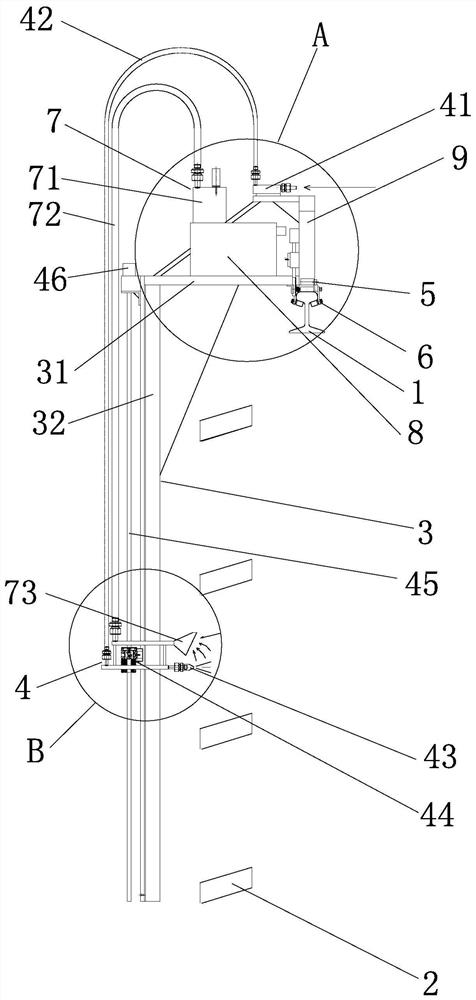
[0056] like Figure 1 to Figure 4 As shown, the present invention provides a dust-removing device for a driving motorcycle circuit. The driving motorcycle circuit includes a driving track 1 and a copper bar 2 located below the driving track 1. The copper bar 2 is a long strip, and the copper bar 2 is The longitudinal direction is along the extending direction of the running track 1 . The ash cleaning device of the present invention includes a base frame 3, and a blowing mechanism 4 and a traveling mechanism 5 installed on the base frame 3; On the track 1, the vertical frame 32 extends downward from one side of the driving track 1; the air blowing mechanism 4 includes an air source inlet 41, a jet gun 43 arranged on the vertical frame 32, and the air source inlet 41 and the jet gun 43. The air intake pipe 42, the jet gun 43 is used to blow air to the copper bar 2; the traveling mechanism 5 includes a traveling wheel 51 installed on the transverse frame 31 and a traveling driving mechanism that drives the traveling wheel 51 to roll, and the traveling wheel 51 is used for driving. Scroll on track 1.
[0057] like figure 1 shown, figure 1It is a view of the cross-sectional direction of the driving track 1 and the copper bar 2. The position of the jet gun 43 is determined according to the position of the copper bar 2 to ensure that the jet gun 43 can be aligned with the copper bar 2. The air blowing port of the jet gun 43 is preferably rotatable. The structural form is so that the blowing angle of the jet gun 43 can be adjusted. The position where the traveling wheel 51 is pressed against the driving track 1 can be determined according to the specific structure of the driving track 1. In this embodiment, as figure 1 As shown, the traveling wheel 51 is pressed against the upper end surface of the traveling track 1 . Preferably, in this embodiment, the traveling driving mechanism includes a motor for driving the traveling wheel 51 to roll, thereby driving the ash cleaning device to travel along the traveling track 1 . When the ash cleaning device walks along the driving track 1, the stability of the ash cleaning device should be ensured. Specifically, the weight distribution of the ash cleaning device itself can be controlled to control the stability of the ash cleaning device on the driving track 1. A special structure is arranged on the ash device to ensure the stability of the ash cleaning device on the driving track 1 .
[0058] The working principle of the ash cleaning device of the present invention is as follows: when the ash cleaning device is installed, the horizontal frame 31 of the base frame 3 is placed above the driving track 1, and the vertical frame 32 is suspended from one side of the driving track 1 under the driving track 1. , to ensure that the air blowing port of the jet gun 43 is aligned with the copper bar 2, the traveling wheel 51 is pressed against the driving track 1, and the power supply is turned on; the air source inlet 41 of the air blowing mechanism 4 is connected with the external compressed air; The air is introduced into the air source inlet 41, and the compressed air is ejected from the air blowing port of the jet gun 43 to blow air to the copper bar 2, thereby cleaning dust and dust; The ash cleaning device is driven to move along the running track 1 , and the jet gun 43 moves along the copper bar 2 , thereby completing the blowing and dust removal of the entire copper bar 2 . The ash cleaning device of the present invention can automatically and efficiently clean and dedust the copper bar 2, the structure accepts orders, the operation is simple and convenient, a large number of manual operations are reduced, the ash cleaning efficiency is high, and the work is safe and reliable.
[0059] As a preferred design, in this embodiment, as figure 1 As shown, the ash cleaning device also includes a control mechanism installed on the base frame 3, and the control mechanism is connected with the travel drive mechanism to control the action of the travel drive mechanism. Further preferably, in this embodiment, the control mechanism is installed in the In the control cabinet 8, in order to ensure the protection level of the control mechanism and prevent the interference of dust. Further preferably, the ash cleaning device further includes a remote controller, and the control mechanism can receive the instructions of the remote controller, thereby realizing the remote control operation of the ash cleaning device, which is flexible and convenient to use.
[0060] In the ash cleaning device of the present invention, the jet guns 43 of the air blowing mechanism 4 can be fixedly installed. When there are multiple copper bars 2 of the driving motor circuit, the plurality of copper bars 2 are arranged in parallel with each other, and the number of the jet guns 43 is the same as the The copper bars 2 are the same, and the jet guns 43 are fixedly installed on the vertical frame 32 and correspond to the copper bars 2 one-to-one, so as to realize the simultaneous purging of the plurality of copper bars 2 .
[0061] As a preferred design, in this embodiment, as figure 1 and Figure 4 As shown, the air gun 43 of the air blowing mechanism 4 can move up and down along the vertical frame 32, and the air blowing mechanism 4 also includes an air gun drive assembly for driving the air gun 43 to move, and the air gun drive assembly is connected with the control mechanism, and the air The number of guns 43 can be one or more. In this embodiment, the number of air-jet guns 43 is one. The mechanism controls the action of the jet gun drive assembly, and drives the jet gun 43 to reciprocate and linearly move up and down, so as to realize the cleaning and dust removal of the multiple copper bars 2, the structure is compact, and the use is flexible and convenient.
[0062] As a preferred design, in this embodiment, as figure 1 and Figure 4 As shown, the jet gun drive assembly includes a lead screw 45 mounted on the base frame 3 and arranged along the vertical frame 32, a lead screw nut assembly 44 mounted on the lead screw 45, and a drive source 46 for driving the lead screw 45 to rotate , the drive source 46 is connected with the control mechanism, the air gun 43 is fixedly installed on the lead screw nut assembly 44, the lead screw nut assembly 44 and the lead screw 45 form a lead screw transmission structure, the lead screw 45 is driven by the drive source 46 to rotate, and the screw The lever nut assembly 44 drives the jet gun 43 to move up and down along the vertical frame 32. In this embodiment, the driving source 46 is a motor. The lead screw 45 is preferably parallel to the vertical frame 32. The lead screw nut assembly 44 includes a sliding block 47. The vertical frame 32 is provided with a sliding rail matched with the sliding block 47. When the lead screw 45 rotates, the lead screw nut The assembly 44 moves up and down along the vertical frame 32 through the slider 47 , thereby ensuring that the lead screw nut assembly 44 can drive the air gun 43 to move up and down smoothly.
[0063] As a preferred design, in this embodiment, as figure 1 , figure 2 and Figure 4 As shown, the dust cleaning device further includes a vacuuming mechanism 7 mounted on the base frame 3, and the vacuuming mechanism 7 includes a vacuuming cabinet 71, a vacuuming port 73 near the air jet 43, and a vacuuming cabinet 71 and a vacuuming port connected 73 of the vacuum hose 72. The dust collector 71 has a structure for generating suction, and through the dust suction pipe 72 and the dust suction port 73, the dust blown off the copper bar 2 is sucked into the dust collector 71 in time, so as to realize the synchronization of blowing and suction, and reduce the dispersion caused by dust. pollution in the air. The connection relationship and installation distance between the dust suction port 73 and the jet gun 43 can be determined according to the actual use situation. Specifically, when the jet gun 43 is fixedly installed, the dust suction port 73 can be fixedly installed near the jet gun 43; When it can move up and down along the vertical frame 32, the dust suction port 73 is fixed with the jet gun 43 and keeps moving synchronously. Specifically, in this embodiment, as figure 1 and Figure 4 As shown, the dust suction port 73 is fixedly connected to the jet gun 43 . The dust suction port 73 is preferably a bell mouth to increase the dust suction effect. The dust collecting cabinet 71 is preferably installed in the horizontal frame 31, and the center of gravity of the dust cleaning device is located above the driving track 1 after the dust cleaning device is installed, so as to ensure the stability of the dust cleaning device.
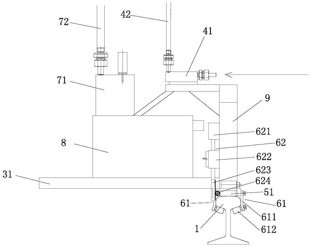
[0064] As a preferred design, in this embodiment, as figure 1 , figure 2 and image 3 As shown, the ash cleaning device also includes a stabilization mechanism 6 installed on the transverse frame 31. When the transverse frame 31 is placed on the driving track 1, the stabilization mechanism 6 can abut against the driving rail 1 to stabilize the transverse frame 31 on the driving track. 1, to ensure the stability of the cleaning device when it moves along the driving track 1, and prevent the cleaning device from tilting during the movement of the cleaning device on the driving track 1, so as to ensure the dust removal effect.
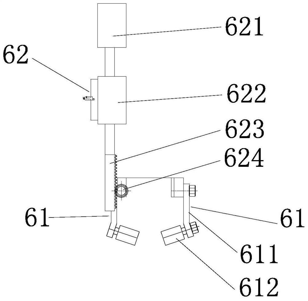
[0065] The stabilization mechanism 6 can adopt a variety of existing structures, and can be selected according to the structure of the driving track 1, so as to stabilize the transverse frame 31 on the driving track 1 to prevent the ash cleaning device from tilting during the moving process on the driving track 1. Alternatively, for example, the stabilization mechanism 6 may adopt two clamping plates abutting on the upper and lower sides or the left and right sides of the running track 1, or a similar structure. As a preferred design, in this embodiment, as figure 2 and image 3 , the traveling wheel 51 is used to press against the upper end face of the driving track 1; the stabilizing mechanism 6 includes two stabilizing wheel assemblies 61 respectively located on both sides of the traveling track 1, and a rotating drive assembly 62 installed on the transverse frame 31. The stabilizing wheel assembly 61 includes a bracket 611 mounted on the transverse frame 31, and a stabilizing wheel 612 rotatably mounted on the bracket 611. The two stabilizing wheels 612 are used to abut on the surface of the running track 1 facing the lower side. At least one bracket 611 of the stabilizing wheel assembly 61 in the assembly 61 is rotatably mounted on the transverse frame 31 and is driven to rotate by the rotating driving assembly 62 .
[0066] Specifically in this embodiment, as figure 2 shown, with figure 2 The left-right direction of the middle drawing is the left-right direction of the ash cleaning device. The cross-sectional shape of the driving track 1 is an "I" shape, and the "I"-shaped driving track 1 is divided into an upper section and a lower section. The traveling wheel 51 is used for pressing against On the upper end surface of the upper section of the running track 1 ; two stabilizing wheels 612 abut on the left and right sides of the lower end surface of the upper section of the running track 1 . The transverse frame 31 includes a mounting bracket 9, the bracket 611 of the stabilizing wheel assembly 61 located on the right side is fixedly installed on the mounting bracket 9, and the bracket 611 of the stabilizing wheel assembly 61 located on the left side is rotatably mounted on the mounting bracket 9, The traveling wheel 51 is installed at the lower end of the mounting frame 9, and adopts the stable structure in this embodiment, refer to figure 2 and image 3 As shown in the figure, before the ash cleaning device is installed, the stabilizing wheel assembly 61 on the left side is adjusted by rotating the drive assembly 62 to rotate to the open state. The fixed wheel assembly 61 fixedly installed on the right side is clamped on the edge of the upper section of the driving track 1, and its stabilizing wheel 612 is pressed against the right side of the lower end face of the upper section of the driving track 1, and then the left side is adjusted by rotating the driving assembly 62. The stabilizing wheel assembly 61 is rotated until its stabilizing wheel 612 is pressed against the left side of the lower side surface of the upper section of the running track 1, and is fixed. In this way, the two stabilizing wheel assemblies 61 and the traveling wheel 51 are used to securely install the base frame 3 on the driving track 1, which is flexible and convenient to use. During the moving process of the ash cleaning device, the stabilizing wheel 612 rolls on the driving track 1, reducing the need for cleaning. Frictional resistance of the ash device. The stabilization mechanism 6 in this embodiment is not limited to be applied to the driving track 1 with an "I"-shaped cross-sectional shape. Based on the same principle, it can also be applied to the driving track 1 with other cross-sectional shapes, ensuring that the two stabilizing wheels 612 press against each other. It suffices to lean on the surface of the running track 1 facing the lower side.
[0067] As a preferred design, in this embodiment, as figure 2 and image 3 As shown, the rotational drive assembly 62 of the stabilizing mechanism 6 includes a telescopic power cylinder 621, a rigid rack 623 mounted on the piston rod of the telescopic power cylinder 621, and a gear 624 fixedly connected with the rotatable bracket 611. The rigid rack 623 It is meshed and connected with the gear 624. When the gear 624 rotates, it drives the bracket 611 to rotate. Through the telescopic movement of the piston rod of the telescopic power cylinder 621, it drives the rigid rack 623 to move in a straight line. The rigid rack 623 drives the gear 624 to rotate through the meshing transmission, and the gear 624 drives The bracket 611 rotates synchronously. As a preferred design, the rotary drive assembly 62 further includes a stroke controller 622, which is used to control the movement stroke of the piston rod of the telescopic power cylinder 621, thereby controlling the rotation range of the stabilizing wheel assembly 61 and ensuring the installation quality. The telescopic power cylinder 621 can be an air cylinder, a hydraulic cylinder or an electric cylinder. Specifically, in this embodiment, the telescopic power cylinder 621 is an air cylinder. The cylinder is vertically installed on the side of the mounting frame 9, and the piston of the cylinder can be controlled by the cylinder control valve opening button. The rod moves up and down. Of course, in other embodiments, the rotation driving assembly 62 may adopt other driving modes, such as motor driving and the like.
[0068] The present invention also provides a dust cleaning method for a driving motorcycle electric circuit. The driving motorcycle electric circuit includes a driving rail 1 and a copper bar 2 located below the driving rail 1. The length direction of the copper bar 2 is along the extending direction of the driving rail 1. Adopt the above-mentioned ash cleaning device to carry out, including the following steps:
[0069] S1, install the ash cleaning device, put the horizontal frame 31 of the base frame 3 on the driving track 1, and the vertical frame 32 extends downward from one side of the driving track 1, and the traveling wheel 51 is pressed against the driving track 1; The blowing port of the jet gun 43 is aligned with the copper bar 2;
[0070] S2, connect the air source inlet 41 of the air blowing mechanism 4 with the external compressed air, the compressed air is passed into the air source inlet 41, and the air gun 43 blows air to the copper bar 2;
[0071] S3. Control the action of the traveling drive mechanism, drive the traveling wheel 51 to roll, the traveling wheel 51 drives the ash cleaning device to move along the driving track 1, and the jet gun 43 moves along the copper bar 2 for ash cleaning.
[0072] The ash cleaning method of the present invention can be applied to the driving motorcycles in various dusty workshops, especially the driving motorcycles in steel-making workshops. The air source inlet 41 of the air blowing mechanism 4 can be connected to the existing workshops. The compressed air pressure is preferably 5-10 bar, especially, taking the use of the dust cleaning device in this embodiment to carry out dust cleaning and dust removal as an example, the dust cleaning method is specifically described as follows:
[0073]Step S1 is specifically as follows: installing the ash cleaning device, placing the horizontal frame 31 of the base frame 3 above the driving track 1, the traveling wheel 51 pressing against the upper end face of the driving track 1, and the vertical frame 32 hanging under the driving track 1, Use the two stabilizing wheel assemblies 61 of the stabilizing mechanism 6 to firmly clamp the base frame 3 against the driving track 1; the ash cleaning device is connected to the power supply, and commands are issued by the remote controller, and the control mechanism in the control cabinet 8 controls the air gun drive assembly. When the driving source 46 is actuated, the screw rod 45 rotates, and the nut assembly of the screw rod 45 drives the air gun 43 to move, so that the air blowing port of the air gun 43 is aligned with the copper bar 2 .
[0074] Step S2 is specifically: connecting the air source inlet 41 of the air blowing mechanism 4 with the external compressed air, the compressed air is introduced into the air source inlet 41, and the air jet 43 blows the copper bar 2; The port 73 sucks the dust swept off from the copper bar 2, and enters the dust collecting cabinet 71 through the dust suction pipe 72;
[0075] Step S3 is specifically as follows: the operator stands in the safe area, uses the remote controller to issue instructions to the control mechanism in the control cabinet 8, the control mechanism controls the reciprocating rotation of the motor in the air gun drive assembly, the motor drives the lead screw 45 to reciprocate and rotate, and the air gun 43 reciprocates. Moving up and down along the vertical frame 32 reciprocatingly, purging and cleaning the multiple copper bars 2 back and forth. Specifically, the stroke of the jet gun 43 moving up and down can be set to 0-2000mm; at the same time, the control mechanism controls the travel drive mechanism. The motor acts to drive the traveling wheels 51 to roll on the driving track 1, and drive the ash cleaning device to move along the driving track 1;
[0076] It can be seen from the above that the ash cleaning device of the present embodiment has a simple structure and can be guaranteed to have a lighter weight, and the overall mass can be less than 25kg, which increases the safety of the ash cleaning device; The ash device can move on the automatic driving track 1 with stable and reliable movement, and realizes the overall cleaning of multiple copper bars 2 at the same time. The cleaning quality is good, the work efficiency is high, and the manual operation is reduced. It can effectively improve the construction work environment and reduce dust dispersion.
[0077] To sum up, the invention effectively overcomes various shortcomings in the prior art and has high industrial utilization value.
[0078] The above-mentioned embodiments merely illustrate the principles and effects of the present invention, but are not intended to limit the present invention. Anyone skilled in the art can modify or change the above embodiments without departing from the spirit and scope of the present invention. Therefore, all equivalent modifications or changes made by those with ordinary knowledge in the technical field without departing from the spirit and technical idea disclosed in the present invention should still be covered by the claims of the present invention.