Particle combustion furnace

A combustion furnace and pellet fuel technology, applied in kitchen utensils, home utensils, roasters/barbecue grills, etc., can solve the problems of complex structure, inconvenient use, poor ash falling efficiency and effect

Pending Publication Date: 2021-04-09
郑颖
View PDF9 Cites 1 Cited by
  • Summary
  • Abstract
  • Description
  • Claims
  • Application Information

AI Technical Summary

Problems solved by technology

[0002] Existing pellet burning stoves, such as barbecue grills, use a burner that is basically a closed bottom structure. After each use, the ashes after the pellet fuel is burned are cleaned by a vacuum cleaner, which is very inconvenient and the user experience is not good. good
Another example is a heating furnace, which is generally equipped with a layer of grate for falling ash, but the pellet fuel of biomass is generally an extruded cylindrical structure with a diameter of 4-6mm and a length of 1-6cm, and the pellet fuel burns to produce If there is no external force, the ash will remain cylindrical, so it is difficult to fall directly, resulting in poor ash fall efficiency and effect. After burning for a long time, it still needs other components to assist in breaking up the ash to clean it. Not only the structure It is more complicated, the production cost is higher, and it requires user participation, so it is not convenient to use

Method used


Image

  • Particle combustion furnace
  • Particle combustion furnace
  • Particle combustion furnace

Examples


Embodiment 1

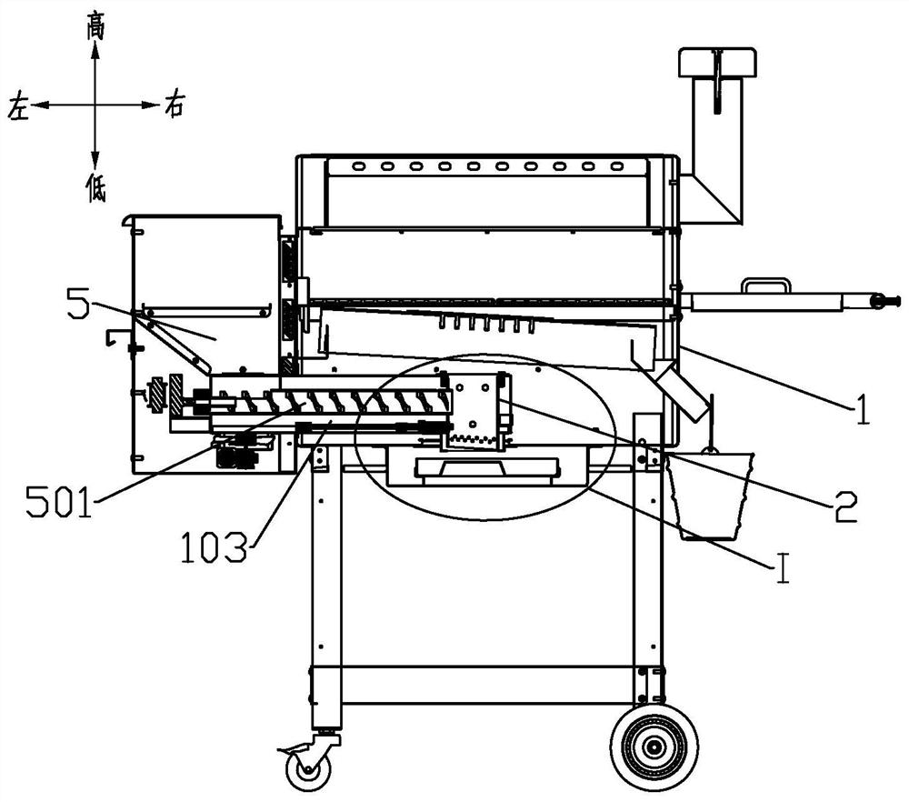
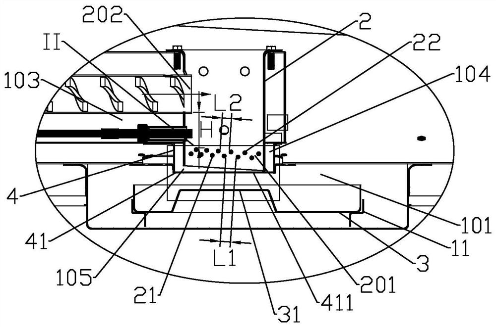
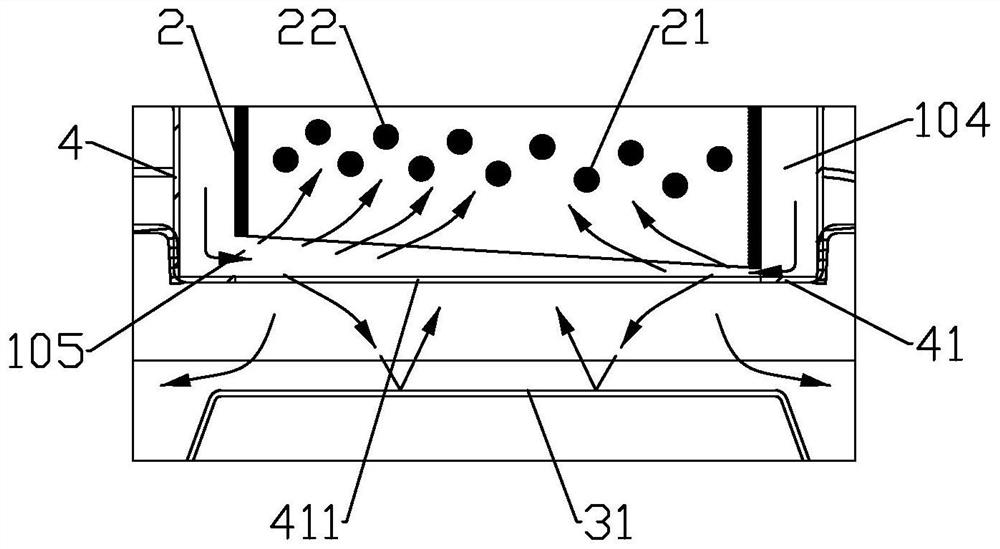
[0032] The present invention provides a particle combustion furnace, such as Figure 1 to Figure 6 As shown, including the body of furnace 1, the body of furnace 1 is provided with a burner 2, the top of the burner 2 is open, the side wall of the burner 2 is provided with a feed port 202, the outside of the body of furnace 1 is provided with a fuel hopper 5, and the fuel A feed channel 501 is provided between the bucket 5 and the feed port 202, and the bottom surface of the burner is provided with a through-hole for air intake and ash fall, and a grid structure supporting the granular fuel 9 is provided above the through-hole, and the grid structure includes The first layer of support 21 and the second layer of support 22 fixed to the burner 2, the first layer of support 21 is lower than the adjacent second layer of support 22, the second layer of support 22 is opposite to the first layer of support 21 are staggered in the vertical direction, and there is a first channel 201 b...

Embodiment 2

[0044] like Figure 7 As shown, the grid structure in this embodiment is formed by wavy sheet metal parts, the wavy troughs on the sheet metal parts form the first layer of support 21, and the wavy peaks on the sheet metal parts form the second layer The supporting body 22 is provided with a through hole forming the first channel 201 between the trough and the crest on the sheet metal part. The outer circumference of the sheet metal part can be adapted to the inner side wall of the burner 2, so there may be no interval mentioned in the first embodiment. In order to prevent ashes from accumulating on the first-layer support body 21, the upper surface of the first-layer support body 21 can be designed as a convex arc surface as much as possible.

[0045] For other content not described in this embodiment, reference may be made to Embodiment 1.

Embodiment 3

[0047] In addition to setting two layers of support, you can also increase the number of layers on this basis, such as Figure 8 As shown, the grid structure also includes a third layer of support 23 fixed to the burner 2, the third layer of support 23 is higher than the second layer of support 22, the gap between the third layer of support 23 and the second layer of support 22 There is a second channel 203 between them, the width W2 of the second channel 203 is smaller than D, and the distance L3 between two adjacent third-layer supports 23 is larger than D and smaller than 2D. It is understandable that according to actual needs, the number of layers of the support body can be increased, and the ash falling effect will be better.

[0048] For other content not described in this embodiment, reference may be made to the foregoing embodiments.


PUM


Abstract

The invention discloses a particle combustion furnace, belongs to the field of combustion equipment, solves a problem of inconvenience in ash removal or poor ash falling effect of a combustor in the prior art, and adopts the technical scheme that a through hole for air intake and ash falling is formed in the bottom surface of the combustor, and a grid structure is arranged above the through hole; the grid structure comprises a first-layer supporting body and a second-layer supporting body which are fixed to the combustor, the first-layer supporting body is lower than the adjacent second-layer supporting body, the second-layer supporting body is distributed in a staggered mode in the vertical direction relative to the first-layer supporting body, and a first channel is formed between the first-layer supporting body and the second-layer supporting body; the width of the first channel is smaller than the diameter D of granular fuel, a distance L2 between every two adjacent second-layer supporting bodies is larger than D and smaller than 2D, the feeding port is located above the grid structure, the height difference is H, H is not smaller than 3D, and an ash receiving disc is arranged at the position, located below the combustor, of the bottom of the furnace body. The particle combustion furnace is mainly used for automatic ash falling, good in ash falling effect and convenient for users to clean ash.

Description

technical field [0001] The invention relates to combustion equipment, in particular to a particle combustion furnace. Background technique [0002] Existing pellet burning stoves, such as barbecue grills, use a burner that is basically a closed bottom structure. After each use, the ashes after the pellet fuel is burned are cleaned by a vacuum cleaner, which is very inconvenient and the user experience is not good. good. Another example is the heating furnace, which generally has a layer of grate for ash falling, but the pellet fuel of biomass is generally an extruded cylindrical structure with a diameter of 4-6mm and a length of 1-6cm, and the pellet fuel burns to produce If there is no external force, the ash will remain cylindrical, so it is difficult to fall directly, resulting in poor ash fall efficiency and effect. After burning for a long time, it still needs other components to assist in breaking up the ash to clean it. Not only the structure It is more complicated,...

Claims


Application Information

Patent Timeline
Patent Type & Authority Applications(China)
IPC IPC(8): A47J37/06
CPCA47J37/06
Inventor 郑颖
Owner 郑颖
Why Eureka
Try Eureka