
Drilling auxiliary tool

A technology for auxiliary tools and mounting holes, which is used in manufacturing tools, drilling/drilling equipment, metal processing equipment, etc. Effect

Active Publication Date: 2020-11-20
HUNAN LIANZHI BRIDGE & TUNNEL TECH
View PDF7 Cites 2 Cited by
  • Summary
  • Abstract
  • Description
  • Claims
  • Application Information

AI Technical Summary

Problems solved by technology

There are the following disadvantages in the existing quasi-starting method: 1. The method of directly drawing points with a marker pen needs to put the equipment on the drilling plane. ;2. There is a certain error in the drilling of the marker pen. If the drilling technology is not skilled enough, it may cause the hole position to shift and form a waste hole. In the end, it is necessary to re-select the position to drill; 3. Use the steel ruler to measure the distance and then drill Although the method of drawing points on the hole plane according to the size can control the hole spacing more accurately, the angular relationship between the hole positions is difficult to grasp, and it is easy to cause the hole position to deviate; 4. The traditional drilling depth control method, the drilling process The dust in the middle will cover the marks, and after the drill has been used for many times, the marks will be difficult to identify, and the marks made each time will interfere with each other, affecting the accurate identification of the drilling depth

Method used


Image

  • Drilling auxiliary tool
  • Drilling auxiliary tool
  • Drilling auxiliary tool

Examples


Embodiment Construction

[0025] The embodiments of the present invention will be described in detail below with reference to the accompanying drawings, but the present invention can be implemented in various ways defined and covered by the claims.

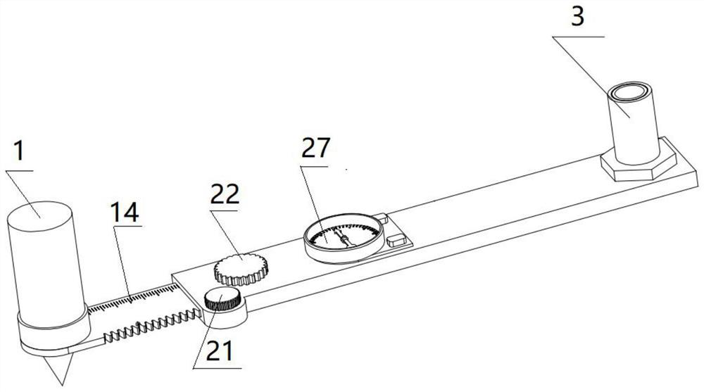
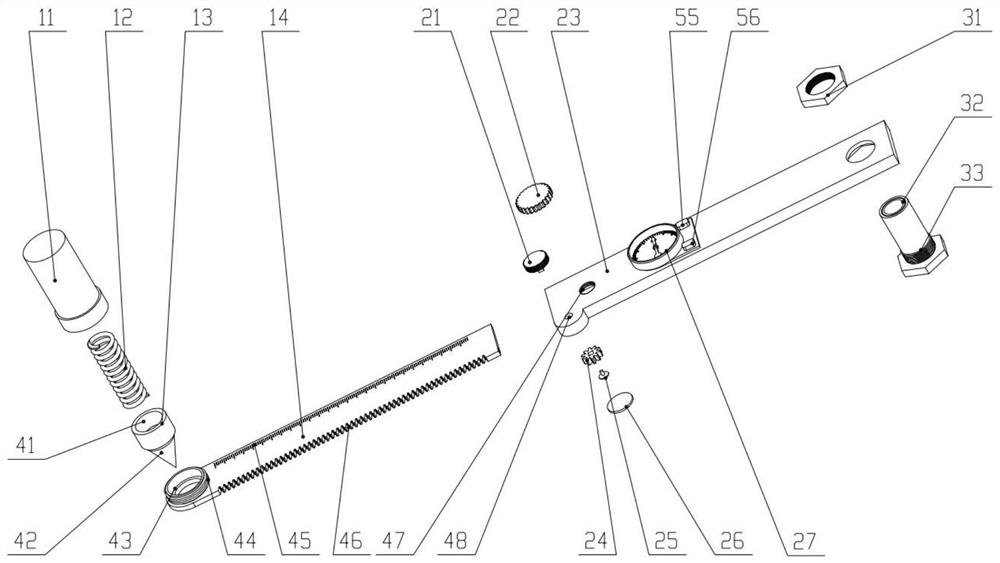
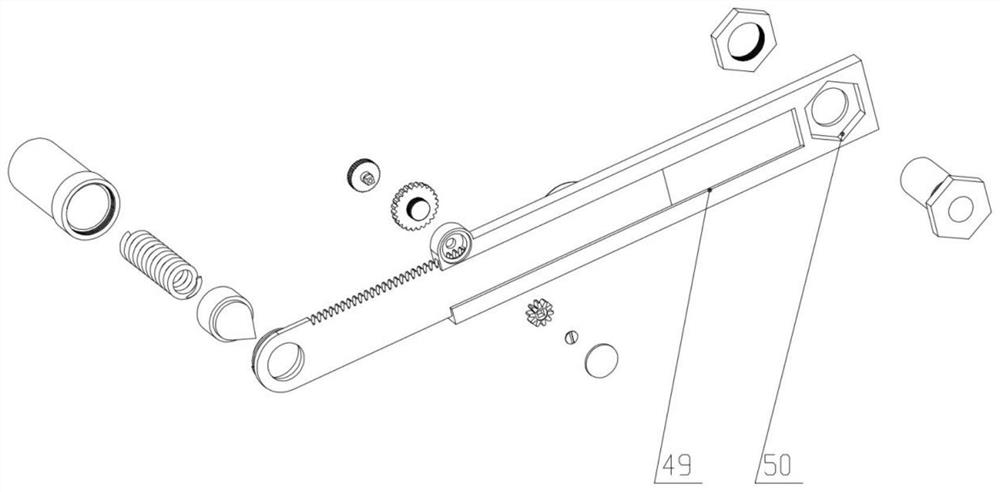
[0026] see Figure 1 to Figure 6 , a drilling auxiliary tool, including a measuring scale body, a positioning device 1 and a control sleeve 3; the measuring scale body includes a scale scale body and a guide rail scale body, and one side of the scale scale body along the length direction is provided with a size scale, and the scale scale There is a mounting hole in the head of the body for installing the positioning device. The positioning device includes a thimble, a spring and a handle. One end of the thimble is conical (conical), and the other end of the thimble is cylindrical. The diameter of the cone is smaller than the diameter of the cylinder. The cone of the thimble The shape passes through the installation hole of the scale body. There is a pit on...


PUM


Abstract

The invention discloses a drilling auxiliary tool. The drilling auxiliary tool comprises a measuring ruler body, a positioning device and a control sleeve, wherein the measuring ruler body comprises ascale body and a guide rail ruler body; one side, in the length direction, of the scale body is provided with a size scale; a mounting hole is reserved in the head of the scale body for mounting thepositioning device; the positioning device is used for positioning the auxiliary tool; the guide rail ruler body is provided with a guide rail clamping groove; the scale body is slidably mounted on the guide rail clamping groove; the guide rail ruler body is provided with a locking device; the locking device is used for locking the scale body so that the scale body cannot move, and the accuracy ofmeasuring size is effectively ensured; meanwhile, the guide rail ruler body is provided with an angle meter, and the angle meter is used for measuring the angle deflection information; and in addition, a through hole for mounting the control sleeve is reserved at the tail end of the guide rail ruler body, and the control sleeve is used for controlling the drilling depth. The auxiliary drilling tool can quickly and accurately obtain the hole spacing between a hole to be drilled and a positioning hole, as well as an angle of the connecting line of the two holes and the reference line, so that the position to be drilled is found and quickly drilled.

Description

technical field [0001] The invention relates to the technical field of displacement monitoring equipment, in particular, to a drilling auxiliary tool. Background technique [0002] Using an electric drill to drill holes in materials is a very common application in our daily life. Generally, drilling is to install equipment and other objects. In order to make the equipment stable, the depth of the drilled holes needs to meet the requirements, and the hole must be consistent with the requirements. The distance and included angle between the holes are consistent with the installation holes of the equipment; the general conventional drilling method is to place the equipment roughly on the plane to be drilled, then trace the holes on the drilling material with a marker pen, and finally move the Open the equipment and use an electric drill to drill holes according to the marks; or first use a steel ruler to measure the distance between the installation holes of the equipment, and ...

Claims


Application Information

Patent Timeline
Patent Type & Authority Applications(China)
IPC IPC(8): B23B47/00B23B47/28B23Q17/22
CPCB23B47/00B23B47/28B23Q17/22
Inventor 周俊华陈胜吉雷孟飞赵莉
Owner HUNAN LIANZHI BRIDGE & TUNNEL TECH
Learn More