Method and equipment for attitude optimization of milling robot considering minimum contour error

A contour error and milling technology, applied in the field of robot posture optimization calculation, can solve the problems of inability to compensate for robot stiffness change error, contour error optimization, and inability to ensure the highest robot rigidity, and achieve the effect of improving the quality of robot milling.

Active Publication Date: 2021-10-08
HUAZHONG UNIV OF SCI & TECH
View PDF16 Cites 1 Cited by
  • Summary
  • Abstract
  • Description
  • Claims
  • Application Information

AI Technical Summary

Problems solved by technology

[0004] 1. Since this method does not consider the end execution force of the robot, it cannot guarantee the maximum rigidity of the robot in the force direction;
[0005] 2. This method can ensure the minimum displacement deviation of the tool tip point, but since the error of the end position of the robot is generally greater than the contour error, this method cannot guarantee the minimum contour error after machining
[0007] 1. This method does not consider the pre-planning and control of the robot’s terminal position and posture. The purpose is only to ensure that the robot’s terminal position is consistent with the planned position through closed-loop feedback during the processing process; therefore, this method is also a real-time error control of the terminal position, and cannot Ensure the minimum contour error after processing;
[0008] 2. Since the consideration of the static stiffness of the robot in this method is only reflected in the selection of the workpiece position, the workpiece position is not changed during the machining process, and the influence of the cutting force on the stiffness during milling is not considered. Therefore, it is still not possible for machining Errors caused by variations in robot stiffness during the process are compensated for
[0009] It can be seen that the calculation and compensation of the deformation of the robot end in the prior art do not take into account the problem of robot attitude selection in the process of robot milling, nor optimize the contour error, which makes it difficult to further improve the quality of robot milling

Method used


Image

  • Method and equipment for attitude optimization of milling robot considering minimum contour error
  • Method and equipment for attitude optimization of milling robot considering minimum contour error
  • Method and equipment for attitude optimization of milling robot considering minimum contour error

Examples


Embodiment Construction

[0082] In order to make the object, technical solution and advantages of the present invention clearer, the present invention will be further described in detail below in conjunction with the accompanying drawings and embodiments. It should be understood that the specific embodiments described here are only used to explain the present invention, not to limit the present invention. In addition, the technical features involved in the various embodiments of the present invention described below can be combined with each other as long as they do not constitute a conflict with each other.

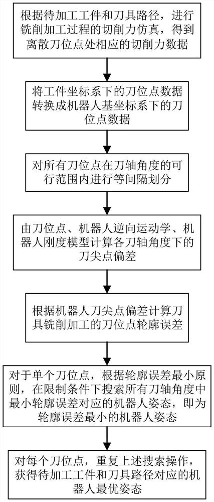
[0083] The evaluation of processing quality should start from the contour error that most directly reflects the processing quality. Therefore, for a specific workpiece to be processed, the present invention proposes a technical idea of ​​simulating the milling force during the milling process and calculating the contour error of the processed workpiece caused by the deformation of the robot end ...


PUM


Abstract

The invention belongs to the field of robot milling, and discloses a method and equipment for optimizing the attitude of a milling robot considering the minimum contour error. The method includes: S1 performing cutting force simulation in the milling process according to the workpiece to be processed and the tool path to obtain cutting force data at discrete tool positions; S2 converting the tool position data in the workpiece coordinate system into the tool position in the robot base coordinate Position point data; S3 divides all tool position points at equal intervals within the feasible range of the tool axis angle; S4 calculates the tool nose point deviation under each tool axis angle; S5 calculates the tool point contour error of the tool milling process; S6 for For a single tool point, according to the principle of minimum tool point contour error, search for the robot posture corresponding to the minimum tool point contour error in all tool axis angles under given restrictions and constraints, and obtain the robot posture with the minimum tool point contour error; S7 repeats S6 for all tool positions to obtain the attitude of the milling robot with the minimum contour error.

Description

technical field [0001] The invention belongs to the field of robot milling processing, and relates to a method and equipment for optimizing the posture of a milling robot considering the minimum contour error, and more specifically, to a robot posture optimization calculation method for considering the optimal contour error of processing engineering in robot milling processing . Background technique [0002] In the field of robot milling, the most important factor affecting the quality of the workpiece is the machining error caused by the end deformation caused by the low rigidity of the robot and the milling force, without considering the error of the robot's motion accuracy. For six-degree-of-freedom serial industrial robots, the problem of low stiffness is a common problem, and its stiffness distribution is heavily dependent on the robot's attitude. [0003] In order to solve the above problems, some scholars proposed a robot structural stiffness performance index that h...

Claims


Application Information

Patent Timeline
Patent Type & Authority Patents(China)
IPC IPC(8): B25J11/00B25J9/16G05B19/41
CPCB25J9/1664B25J11/005G05B19/41
Inventor 杨吉祥林俊哲叶葱葱丁汉
Owner HUAZHONG UNIV OF SCI & TECH
Why Eureka
Try Eureka