Buried charging pile for new energy automobile

A technology of new energy vehicles and charging piles, applied in electric vehicle charging technology, charging stations, electric vehicles, etc., can solve the problems of charging line damage, offset charging line protection, charging line breakage and disconnection, etc., to avoid damage and fracture , improve the service life and prevent damage and fracture

Inactive Publication Date: 2020-11-20
郑州三骏能源科技有限公司
View PDF1 Cites 7 Cited by
  • Summary
  • Abstract
  • Description
  • Claims
  • Application Information

AI Technical Summary

Problems solved by technology

[0003] At present, most of the charging piles are always installed on the ground, no matter whether they are used or not, they will be exposed to the sun, wind and rain, and the charging time of office workers in general life is at night, so that most of the charging piles are not in use during the day. As a result, the charging pile is damaged in vain during the day, resulting in a reduction in service life, and the charging pile is always on the ground and is always threatened by vehicles, and it is very likely to be damaged by impact, so that the charging pile cannot be effectively protected. Therefore, it is urgently needed A charging pile that can increase the service life
[0004] A buried charging pile for new energy vehicles is disclosed in the Chinese invention patent application publication specification CN 110949167 A. Although the buried charging pile for new energy vehicles can lower the charging pile into the buried pit when it is not in use , to protect the charging pile and prolong the service life of the charging pile, but there is a danger of the charging pile shifting left and right during the rising and falling process of the charging pile. Since the charging line is not fixed, the charging pile will The charging line causes damage, which is easy to break and disconnect the charging line. The buried charging pile for new energy vehicles has the disadvantages of offset when the charging pile rises and falls and insufficient protection for the charging line.

Method used


Image

  • Buried charging pile for new energy automobile
  • Buried charging pile for new energy automobile
  • Buried charging pile for new energy automobile

Examples


Embodiment Construction

[0030] The following will clearly and completely describe the technical solutions in the embodiments of the present invention with reference to the accompanying drawings in the embodiments of the present invention. Obviously, the described embodiments are only some, not all, embodiments of the present invention. Based on the embodiments of the present invention, all other embodiments obtained by persons of ordinary skill in the art without making creative efforts belong to the protection scope of the present invention.

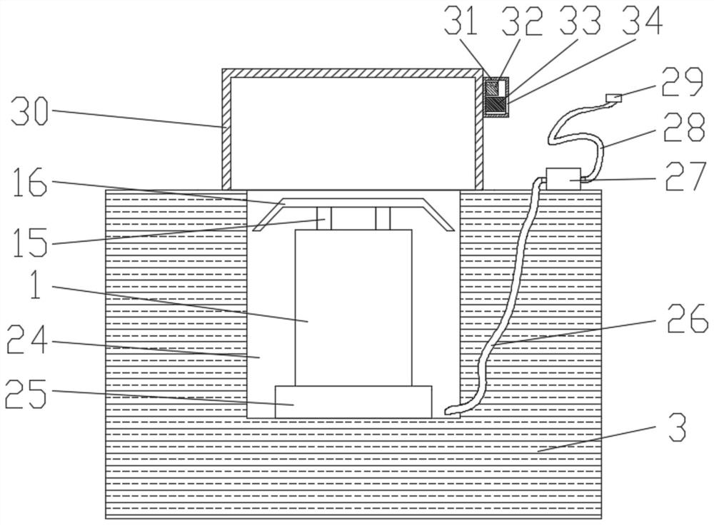
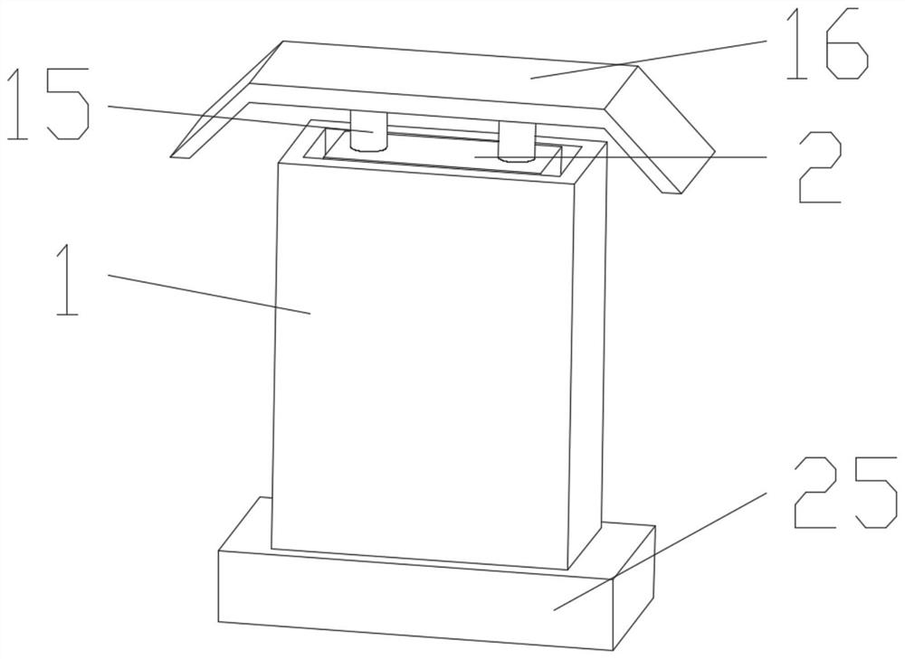
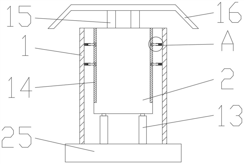
[0031] see Figure 1-8, a buried charging pile for new energy vehicles, comprising a charging pile casing 1, a charging pile body 2 and a surface layer 3, the inner bottom wall of the charging pile casing 1 is fixedly connected to a fixed end of an electrohydraulic push rod 13, and the electrohydraulic push rod 13 is fixedly connected to the fixed end of the electrohydraulic push rod. The movable end of the rod 13 is fixedly connected to the bottom of the char...


PUM


Abstract

The invention discloses a buried charging pile for a new energy automobile, which relates to the technical field of buried charging piles. The buried charging pile for a new energy automobile comprises a charging pile shell, a charging pile body and a ground surface layer, wherein the inner side surface of the charging pile shell is fixedly connected with a limiting cylinder, and the bottom of thelimiting cylinder is fixedly connected with a matching block. The limiting cylinder, the limiting spring and the limiting block are arranged, and thus, the buried charging pile for the new energy automobile has the effect of preventing the charging pile body from deviating when the charging pile body ascends and descends; a limiting cylinder, a matching block, a limiting spring, a limiting block,a roller pin, a roller and a sliding groove are arranged in a matching manner, in the using process, when the charging pile body can ascend and descend, the charging pile body is prevented from deviating, and meanwhile, through the arrangement of the guardrail, the situation that an automobile is parked above a buried pit when the automobile is parked and charged is prevented, the charging pile body is prevented from colliding with the automobile when ascending and descending, and therefore the effect of preventing the charging pile body from deviating when ascending and descending is achieved, and the purpose of improving safety is achieved.

Description

technical field [0001] The invention relates to the technical field of buried charging piles, in particular to a buried charging pile for new energy vehicles. Background technique [0002] With the enhancement of environmental protection awareness and the development of new energy vehicles, the use of charging vehicles is increasing, and the area for setting up car charging piles is more extensive. General residential areas will be equipped with charging piles, so charging piles have become an indispensable part of modern communities. Indispensable electrical equipment; [0003] At present, most of the charging piles are always installed on the ground, no matter whether they are used or not, they will be exposed to the sun, wind and rain, and the charging time of office workers in general life is at night, so that most of the charging piles are not in use during the day. As a result, the charging pile is damaged in vain during the day, resulting in a reduction in service li...

Claims


Application Information

Patent Timeline
Patent Type & Authority Applications(China)
IPC IPC(8): B60L53/31B60L53/30B60L53/18
CPCB60L53/18B60L53/30B60L53/31Y02T10/70Y02T10/7072Y02T90/12Y02T90/14
Inventor 谢晓辉李明娟
Owner 郑州三骏能源科技有限公司
Why Eureka
Try Eureka