
Emergency brake device for rail vehicle

A technology for emergency braking and delivery vehicles, which is applied in the direction of brakes, brake components, transportation and packaging, etc., and can solve the problems that safety requirements cannot be implemented

Pending Publication Date: 2022-02-25
SIEMENS MOBILITY AUSTRIA GMBH
View PDF0 Cites 0 Cited by
  • Summary
  • Abstract
  • Description
  • Claims
  • Application Information

AI Technical Summary

Problems solved by technology

In conventional UIC / RIC passenger compartments, safety requirements are currently not practicable without direct connection of the occupant emergency brake to the compressed air system

Method used


Image

  • Emergency brake device for rail vehicle

Examples


Embodiment Construction

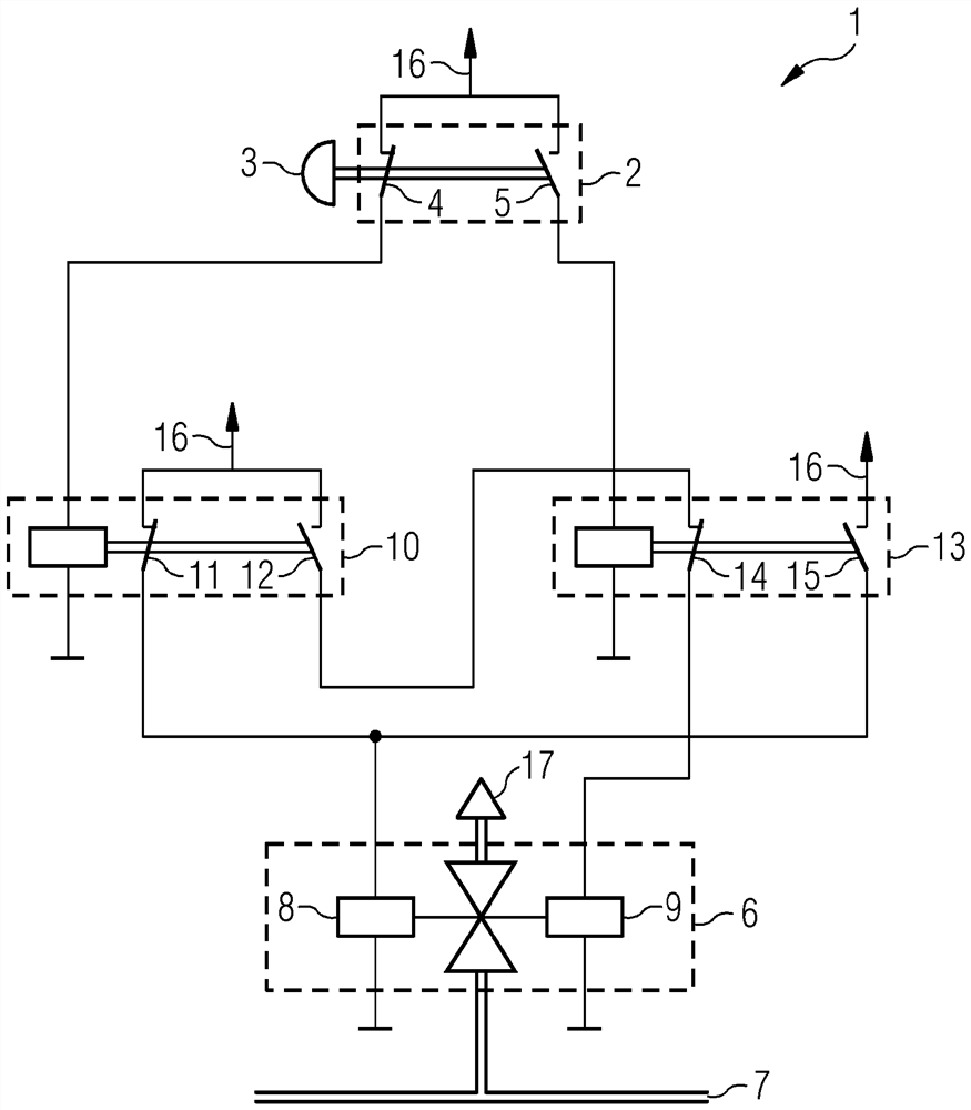
[0016] figure 1 An emergency braking device is shown in an exemplary and schematic manner. The electrical and pneumatic circuit diagram of the emergency braking device 1 is shown. Such an emergency braking device 1 comprises a passenger emergency brake 2 , a bistable electromagnetic compressed air valve 6 , an opening relay 10 and an closing relay 13 . The passenger emergency brake 2 is equipped with a manually operable passenger emergency brake handle 3, which is mechanically coupled with the opening contact 4 and the closing contact 5 and can make these contacts 4, 5 in the rest position (as in figure 1 as shown in ) and the emergency stop position. The compressed air valve 6 is connected pneumatically to the main air line 7 and has an exhaust device 17 through which the compressed air conducted in the main air line 7 can escape to the environment. In this case, the compressed air valve 6 can be switched between a closed position and an open position, for which purpose tw...


PUM


Abstract

The invention relates to an emergency brake device (1) for a rail vehicle having a compressed-air-brake system, wherein a braking process can be initiated by lowering the air pressure in a main air conduit (7) and which has an exclusively electric connection to a passenger emergency brake (2).

Description

technical field [0001] The invention relates to an emergency braking device for rail vehicles equipped with compressed air braking equipment. Background technique [0002] Passenger rail vehicles are equipped with emergency brakes operable by passengers in accordance with the relevant licensing regulations. Its operating principle is based on the manual actuation of the handle to reduce the pressure in the compressed air line, the so-called main air line, which brings the brake pads into contact with the brake disc or rim. In addition, the emergency braking device is equipped with other functions, such as emergency brake override for preventing the vehicle from coming to a standstill on unsuitable road sections, for example in tunnels or on bridges. The function of the emergency brake requires that a main air line or a pipe leading to or connected to the main air line be led to each occupant emergency brake. Since passenger rail vehicles are usually equipped with multiple ...

Claims


Application Information

Patent Timeline
IPC IPC(8): B60T17/20
CPCB60T13/385B60T13/665B60T15/027B60T2270/40B60T17/20B60T13/683
Inventor M·马吉迪M·豪本霍费尔R·施米德特
Owner SIEMENS MOBILITY AUSTRIA GMBH
Learn More