A pump type filling equipment
A filling equipment and water pump technology, which is applied in the field of water pump filling equipment, can solve the problems of easy throwing out of materials in the filling head, and achieve the effect of preventing waste.
- Summary
- Abstract
- Description
- Claims
- Application Information
AI Technical Summary
Problems solved by technology
Method used
Image

Examples
Embodiment 1
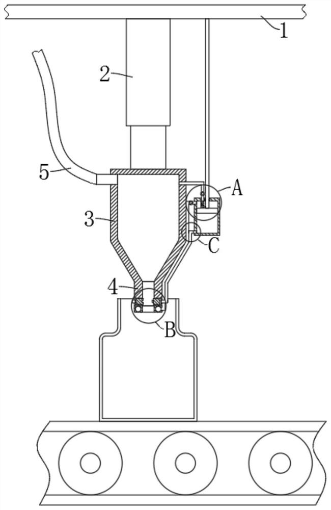
[0029] refer to Figure 1-5 , a water pump type filling equipment, comprising a top plate 1 fixedly connected to the filling equipment, the lower end of the top plate 1 is fixedly installed with a telescopic device 2, the lower end of the telescopic device 2 is fixedly connected with a filling cylinder 3, the filling cylinder 3 The lower end is provided with a vertically downward filling head 4, the upper side wall of the filling cylinder 3 is fixedly connected with a delivery pipe 5 communicating with it, the end of the delivery pipe 5 is connected to the output end of the water pump, and the outer wall of the filling cylinder 3 is fixedly connected There is a device tank 6, a material suction device is provided between the device tank 6 and the lower end of the filling head 4, and an opening and closing device connected to the device tank 6 is provided inside the filling head 4, and the filling device is filled by a telescopic device 2 Carry out up and down reciprocating fil...
Embodiment 2
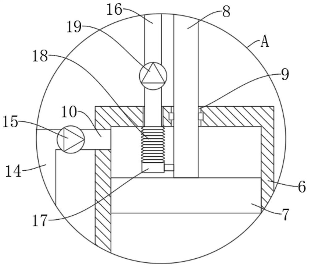
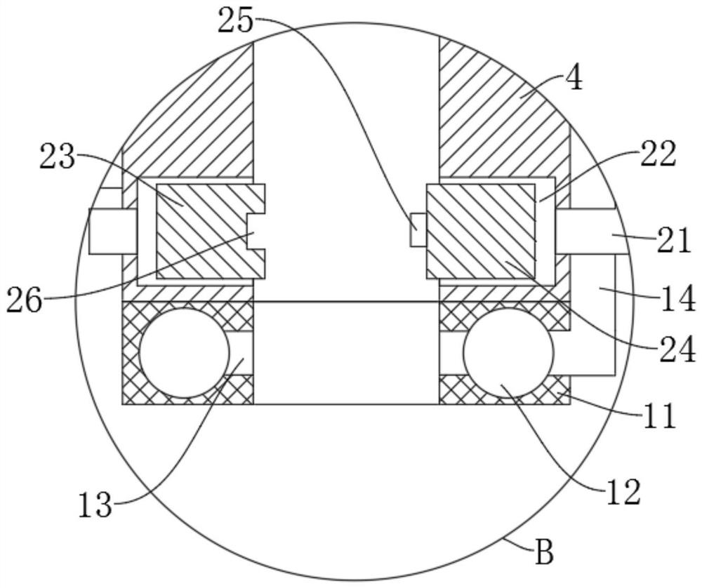
[0034] refer to figure 2 , image 3 and Figure 5 , is basically the same as Embodiment 1, furthermore: the suction device includes a piston 7 that is slidably connected in the device tank 6, the upper end of the piston 7 is fixedly connected with a push rod 8, and the upper end of the push rod 8 is fixed to the lower end of the top plate 1 Connection, the upper end of the device tank 6 is provided with a rod groove 9 matching with the push rod 8, the lower end of the filling head 4 is fixedly connected with an annular block 11, and the interior of the annular block 11 is provided with a cavity 12, and the inner ring side of the annular block 11 The wall is provided with a plurality of suction ports 13 communicating with the cavity 12, the upper end side wall of the device tank 6 is provided with a suction pipe 10, and the first check valve 15 is arranged in the suction pipe 10, and the cavity 12 is connected with the suction pipe 10. The tubes 10 are fixedly connected by t...
Embodiment 3
[0039] refer to image 3 and Figure 4, which is basically the same as in Embodiment 1, furthermore: the opening and closing device includes sliding chambers 22 arranged on the left and right inner walls of the filling head 4, and the two sliding chambers 22 are respectively provided with a left pressing plate 23 and a right pressing plate 24, and the device tank 6 The lower side wall of the lower end is provided with a ventilation tube 20, and the two sliding chambers 22 are fixedly connected and communicated with the ventilation tube 20 through the second connecting tube 21. When the filling head 4 retracts upward, the gas at the lower end of the device tank 6 passes through the second connecting tube 21. The connecting pipe 21 is pressed into the two sliding chambers 22, so that the left pressing plate 23 and the right pressing plate 24 slide out of the two sliding chambers 22 and interfere with each other, thereby realizing the automatic disconnection of the filling head 4...
PUM
 Abstract
Description
Claims
Application Information