
Tamping machine capable of controlling steering direction

A technology of ramming machine and steering mechanism, which is applied in the fields of soil protection, construction, infrastructure engineering, etc., and can solve the problems of scalding staff and staff, inconvenient movement, accidental injury, etc.

Inactive Publication Date: 2020-11-20
柴喜全
View PDF7 Cites 0 Cited by
  • Summary
  • Abstract
  • Description
  • Claims
  • Application Information

AI Technical Summary

Problems solved by technology

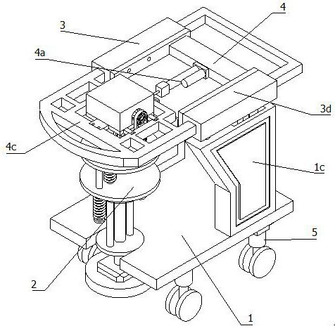
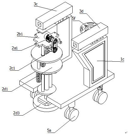
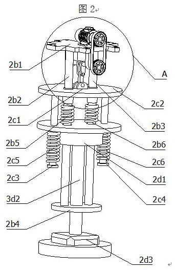
[0002] The tamping machine is a kind of machine used for compaction. It is mostly used for leveling and compacting the foundation during construction. The firepower ram is made according to the principle of a two-stroke internal combustion engine. There are upper and lower pistons in the cylinder, and the upper piston is an internal combustion piston. The lower piston is a buffer piston, and the lower part of the cylinder is equipped with a rammer with an inclined bottom surface, so that the vertical axis of the cylinder is deflected forward. The upper piston rod protrudes from the through hole in the middle of the cylinder top cover, and the lower piston rod protrudes from the lower end of the cylinder. It is integrated with the rammer, the cylinder and the rammer are tensioned by a spring, and a handrail is provided to control the forward direction of the ramming machine. It is off the ground, and under the action of its own weight, it falls to the ground and rams the soil. When the rammer jumps and falls, the fuselage moves forward step by step. When the existing ramming machine for road and bridge construction is not in use, it is relatively heavy , it is not easy to move, and the distance between the engine and the handrail of the existing ramming machine for road and bridge construction is relatively close, which leads to the problem of inadvertently scalding the staff and accidentally injuring themselves due to improper operation. For this reason, we propose a A tamping machine that can control the steering. This equipment can move by itself according to needs, and can be retracted by itself when not in use. It is safe and easy to control.

Method used


Image

  • Tamping machine capable of controlling steering direction
  • Tamping machine capable of controlling steering direction
  • Tamping machine capable of controlling steering direction

Examples


Embodiment Construction

[0033] The following description serves to disclose the present invention to enable those skilled in the art to carry out the present invention. The preferred embodiments described below are only examples, and those skilled in the art can devise other obvious variations.

[0034] refer to Figure 1 to Figure 10As shown, a kind of tamping machine capable of controlling steering includes a frame 1, a tamping machine 2, a lifting mechanism 3, a telescoping mechanism 4, and a steering mechanism 5. The steering mechanism 5 is fixedly installed with the frame 1, and the steering mechanism 5 is fixed. Installed on the lower end of the frame 1, the elevating mechanism 3 is arranged in a vertical state, and the elevating mechanism 3 is fixedly installed on the side of the frame 1 in a symmetrical state. The output end of the elevating mechanism 3 is also fixedly installed with a telescopic mechanism 4, The lower end is fixedly connected with the lifting mechanism 3, and the telescopic...


PUM


Abstract

The invention relates to the field of tamping machines, in particular to a tamping machine capable of controlling a steering direction. The tamping machine comprises a machine frame, a tamping machinebody, a lifting mechanism, a telescopic mechanism and a steering mechanism. The steering mechanism is fixedly disposed on the machine frame and is fixedly disposed at the lower end of the machine frame. The lifting mechanism is vertically disposed and is symmetrically fixedly disposed on the sides of the machine frame. The telescopic mechanism is fixedly disposed at the output end of the liftingmechanism. The lower end of the telescopic mechanism is fixedly connected with the lifting mechanism. The telescopic mechanism is horizontally disposed at the upper end of the telescopic mechanism. The telescopic mechanism is fixedly connected with the tamping machine body. The tamping machine body is vertically disposed. The upper end of the tamping machine body is fixedly connected to the outputend of the telescopic mechanism. The tamping machine can move on its own according to needs and can return on its own when not in use, and the tamping machine is safe and convenient to control.

Description

technical field [0001] The invention relates to the field of ramming machines, in particular to a ramming machine capable of controlling steering. Background technique [0002] The tamping machine is a kind of machine used for compaction. It is mostly used for leveling and compacting the foundation during construction. The firepower ram is made according to the principle of a two-stroke internal combustion engine. There are upper and lower pistons in the cylinder, and the upper piston is an internal combustion piston. The lower piston is a buffer piston, and the lower part of the cylinder is equipped with a rammer with an inclined bottom surface, so that the vertical axis of the cylinder is deflected forward. The upper piston rod protrudes from the through hole in the middle of the cylinder top cover, and the lower piston rod protrudes from the lower end of the cylinder. It is integrated with the rammer, the cylinder and the rammer are tensioned by a spring, and a handrail i...

Claims


Application Information

Patent Timeline
IPC IPC(8): E02D3/046
CPCE02D3/046
Inventor 柴喜全
Owner 柴喜全
Learn More