
Novel movable end supporting device for rolling bearing mill

A technology of rolling bearing and supporting device, which is applied to the rigid bracket, bearing element, shaft and bearing of bearing components, etc., can solve the problems of poor sealing of the sealing device, inability to put the roller in, and the roller is out of the groove, so as to avoid the problem of moving , Simple structure, simple installation effect

Inactive Publication Date: 2014-10-08
SHANDONG ZHANGQIU BLOWER
View PDF7 Cites 1 Cited by
  • Summary
  • Abstract
  • Description
  • Claims
  • Application Information

AI Technical Summary

Problems solved by technology

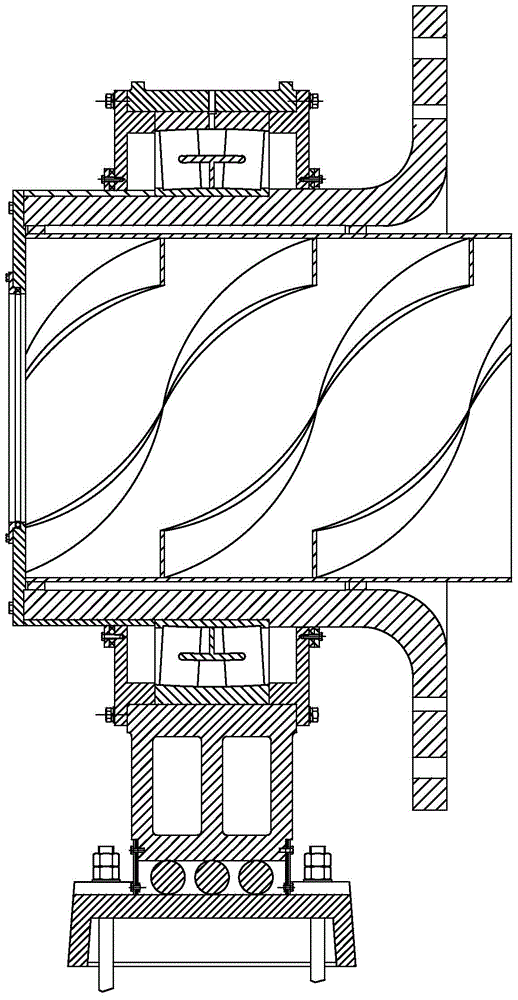
like figure 1 As shown, the support structure of the active end of the bearing mill on the market now mostly uses double-row self-aligning spherical roller bearings for self-alignment, and then a roller groove is processed between the bearing lower seat and the chassis, and several cylindrical rollers are arranged to realize the grinding. The expansion and contraction of the machine cylinder and the fixing of the outer side of the inner ring of the bearing mostly adopt the joint positioning of the bearing sleeve and the spiral cylinder. The above mechanism design has the following problems: ① The structure is complex, and the processing and coordination are difficult to ensure. The axial misalignment of the roller groove often occurs. The phenomenon that the roller cannot be put in; ②During the normal operation of the mill, it is easy for the roller to be stuck in the roller groove and not rotate, causing the vibration of the mill, and even serious mechanical accidents such as the roller falling out of the groove when it is bad; ③Sealing device If the seal is not good, dust can easily enter the roller cavity along the roller groove, contaminating the grease, etc.; 1. The impact and vibration of the material on the spiral cylinder keeps the connecting bolts between the hollow shaft and the spiral cylinder in a state of mixed force, which may cause loosening or breaking of the bolts, or cause the double-row self-aligning spherical roller bearing to escape

Method used


Image

  • Novel movable end supporting device for rolling bearing mill
  • Novel movable end supporting device for rolling bearing mill
  • Novel movable end supporting device for rolling bearing mill

Examples


Embodiment Construction

[0018] In order to clearly illustrate the technical characteristics of this solution, the following describes this solution through a specific implementation and in conjunction with the accompanying drawings.

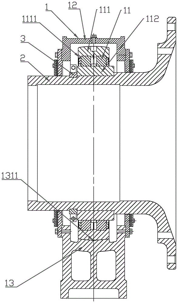
[0019] Such as Figure 2-5 As shown, a novel rolling bearing mill movable end support device of the present invention includes a bearing support body 1 and a hollow shaft 2. The bearing support body 1 and the hollow shaft 2 together constitute the movable end support device of the mill.

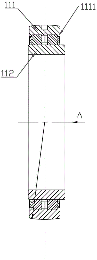
[0020] The bearing support 1 includes a rolling bearing 11, a bearing upper cover 12, and a bearing lower seat 13. The rolling bearing 11 is arranged inside a bearing housing composed of the bearing upper cover 12 and the bearing lower seat 13, and the bearing support The rolling bearing 11 of 1 is sleeved on the hollow shaft 2. The rolling bearing 11 is an outer spherical self-aligning double row cylindrical roller bearing, the bearing outer ring 111 of the rolling bearing is a spherical s...


PUM


Abstract

The invention discloses a novel movable end supporting device for a rolling bearing mill. The novel movable end supporting device comprises a bearing supporting body and a hollow shaft, wherein the bearing supporting body comprises rolling bearings, an upper bearing cover and a lower bearing pedestal; the rolling bearings are arranged in a bearing shell consisting of the upper bearing cover and the lower bearing pedestal; the rolling bearings of the bearing supporting body sleeve a hollow shaft; the rolling bearings are two columns of cylindrical roller self-aligning bearings with outer spherical surfaces; outer bearing rings of the rolling bearings are spherical surfaces; flanges are arranged on two sides of the outer bearing rings; no flange is arranged on inner bearing rings of the rolling bearings; the inner bearing rings are wider than the outer bearing rings; an inner spherical surface matched with the outer bearing rings is formed in the lower bearing pedestal; inner bearing ring fixing devices are arranged on the left sides of the parts, which are combined with the hollow shaft, of the rolling bearings and sleeve an annular slot formed in the hollow shaft. According to the novel movable end supporting device, the shortcomings of a conventional bearing mill movable end supporting structure are overcome; the novel movable end supporting device has the characteristics of simple structure, economy, durability, light weight and convenience in mounting.

Description

Technical field [0001] The invention relates to a supporting device for a rolling bearing mill, in particular to a new type of movable end supporting device for a rolling bearing mill with reasonable structure and practicality. Background technique [0002] Building a conservation-oriented society, reducing energy consumption, compared with traditional mills, rolling bearing mills have the advantages of reduced power consumption, long service life, energy saving when starting, and easy to achieve clean production, so they are gradually recognized by the market. Such as figure 1 As shown, the movable end support structure of bearing mills on the market now uses double-row spherical roller bearings for centering, and then a roller groove is processed between the bearing lower seat and the chassis, and several cylindrical rollers are arranged to achieve grinding. The expansion and contraction of the cylinder body and the fixing of the outer side of the bearing inner ring mostly use ...

Claims


Application Information

Patent Timeline
IPC IPC(8): F16C35/04
Inventor 卢天平赵凤春王林志张鹏部辉
Owner SHANDONG ZHANGQIU BLOWER
Learn More