Building water supply and drainage anti-blocking device

A technology for water supply and drainage and anti-clogging, applied in water supply installations, buildings, drainage structures, etc., can solve the problem that the filter device is not equipped with a filter screen or a real-time filter element cleaning device, etc., to ensure the effect of cleaning

Inactive Publication Date: 2020-11-20
南京迈科拓信息科技有限公司
View PDF1 Cites 5 Cited by
  • Summary
  • Abstract
  • Description
  • Claims
  • Application Information

AI Technical Summary

Problems solved by technology

[0004] Based on the technical problem that the existing filter device does not have a real-time cleaning device for the

Method used


Image

  • Building water supply and drainage anti-blocking device
  • Building water supply and drainage anti-blocking device
  • Building water supply and drainage anti-blocking device

Examples


Example Embodiment

[0028] Example 1

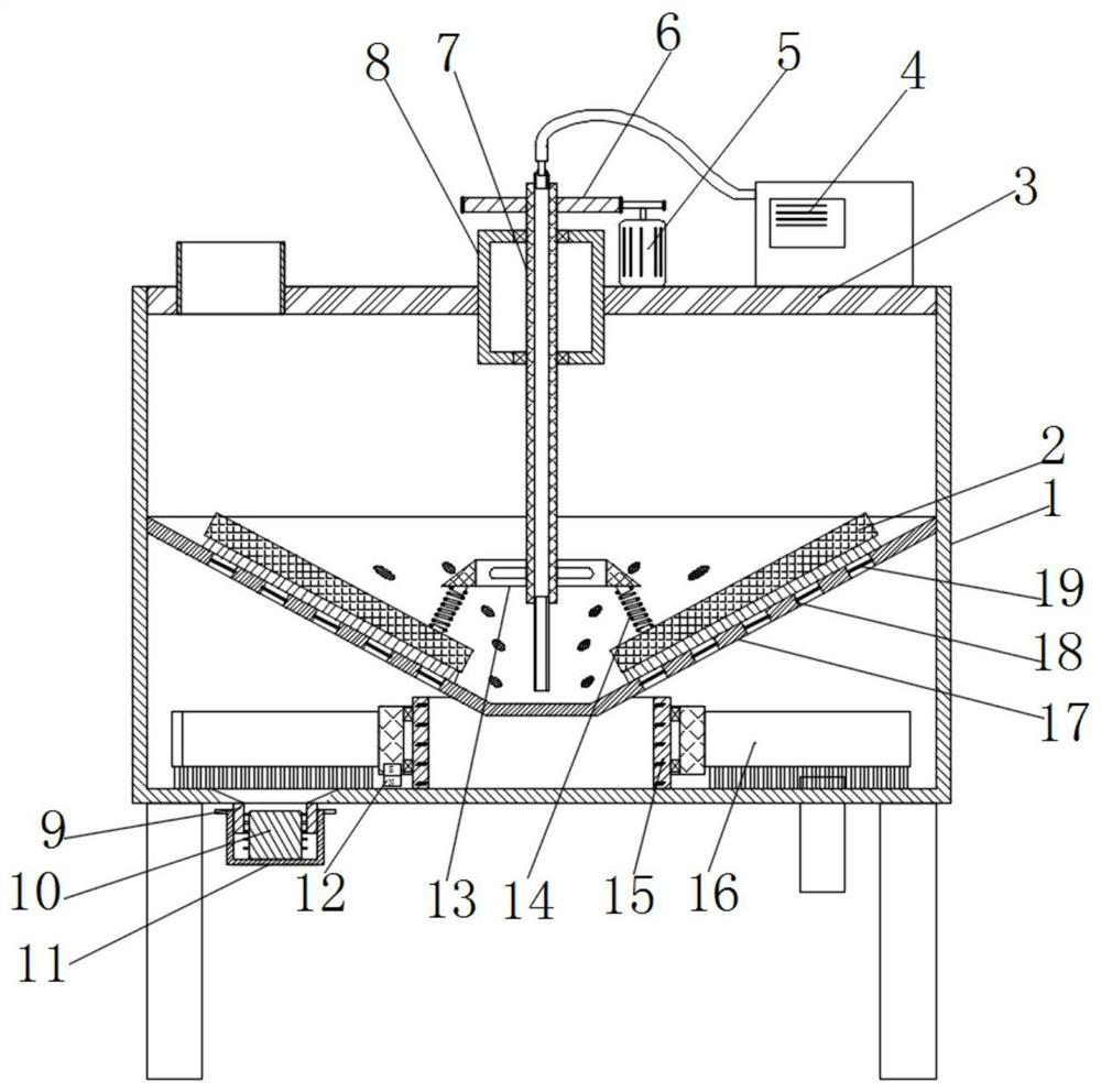
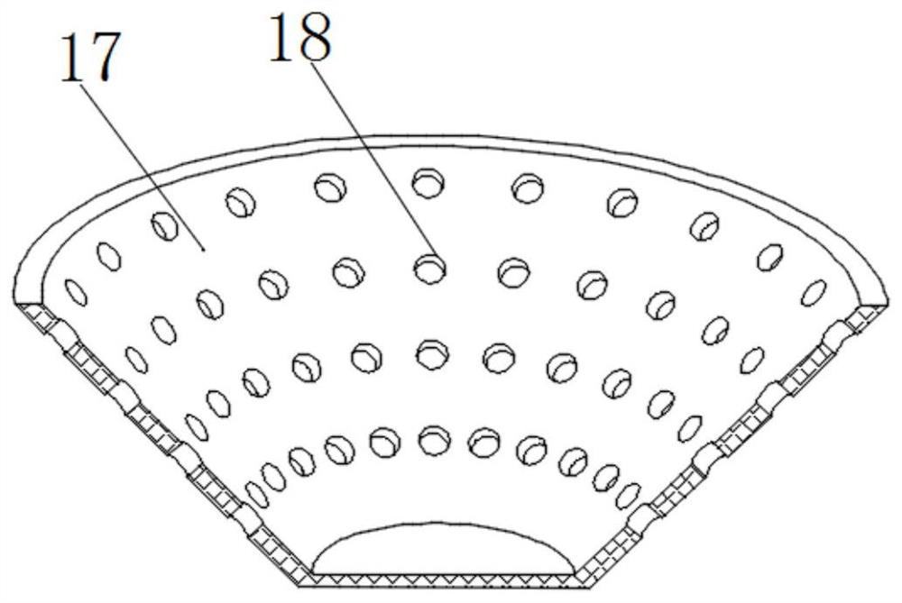
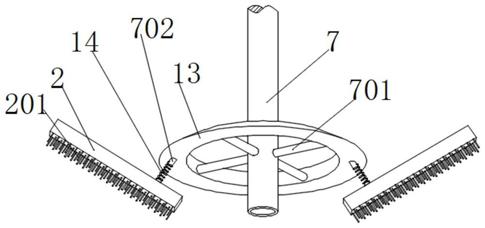
[0029] refer to Figure 1-5 , an anti-clogging device for water supply and drainage of buildings, comprising a fire-fighting pool 1 with a cylindrical structure, the top of the fire-fighting pool 1 is provided with a cover plate 3, and the middle of the cover plate 3 is embedded with a cylindrical cavity. The special bearing seat 8 of the structure, the middle of the special bearing seat 8 is rotatably connected with a transmission tube 7, and the circumferential outer wall of the transmission tube 7 is fixed with four support rods 701 distributed in a centripetal manner near the bottom end. One end of the rod 701 away from the transmission tube 7 is fixed with the same fixing ring 13 , the lower surface of the fixing ring 13 is fixed with two centrally symmetrical fixing projections 702 , and the outer walls of the two fixing projections 702 are sleeved with Springs 14, the bottom ends of the two springs 14 are fixed with inclined brush rods 2, and the low...

Example Embodiment

[0036] Example 2

[0037] refer to Figure 1-3 , an anti-clogging device for water supply and drainage of buildings. Compared with Embodiment 1, the present embodiment also includes a support pipe 15 fixed in the middle of the bottom of the fire pool 1, and a bearing 1603 is fixed on the outer circumferential wall of the support pipe 15 near the upper and lower ends. , the outer wall of the bearing 1603 is fixed with the same rotating ring 1602 .

[0038] Among them, the outer wall of the rotating ring 1602 is fixed with an arc-shaped scraper 16 that is equidistantly distributed and symmetrical to the center, and the bottom end of the arc-shaped scraper 16 is provided with rubber synapses distributed at equal distances, and the bottom end of the rubber synapses is connected to the fire pool. The bottom of the fire fighting pool 1 is in contact with the bottom, so that it is only necessary to drive the rotating ring 1602 to rotate when the fine mud at the bottom of the fire pool...


PUM


Abstract

The invention belongs to the technical field of fire water supply, in particular to a building water supply and drainage anti-blocking device. Aiming at the problem that an existing filtering device is not provided with a real-time cleaning device for a filter screen or a filter element, a scheme as follows is proposed. A fire pool in a cylindrical structure is included, a cover plate is arrangedat the top end of the fire pool, a purpose-made bearing seat internally provided with a cavity in a cylindrical structure is embedded in the middle of the cover plate, a transfer pipe is rotatably connected to the middle of the purpose-made bearing seat, four supporting bars which are distributed in a centripetal mode are fixed to the peripheral outer wall of the transfer pipe and close to the bottom end of the transfer pipe, and the same fixed ring is fixed to the ends, far away from the transfer pipe, of the four supporting bars. When the building water supply and drainage anti-blocking device is used, some garbage is blocked on the filter screen after the water is discharged from the bottom of the fire pool for a period of time, and at the moment, only the transfer pipe needs to be controlled so that a brush rod attached to the surface of a conical filter cylinder is driven to continuously clean the garbage blocked on the filter screen.

Description

technical field [0001] The invention relates to the technical field of fire water supply, in particular to an anti-clogging device for building water supply and drainage. Background technique [0002] Water conservancy projects are projects built to control and allocate natural surface water and groundwater to achieve the purpose of eliminating harm and rejuvenating profits. Also known as water engineering. Water is an indispensable precious resource for human production and life, but its natural state does not fully meet human needs. Only by building water conservancy projects can we control water flow, prevent floods, and regulate and distribute water to meet the needs of people's life and production for water resources. Water conservancy projects need to build different types of hydraulic structures such as dams, dikes, spillways, sluices, water inlets, channels, canals, rafts, and fishways to achieve their goals. [0003] After searching, the Chinese patent number is ...

Claims


Application Information

Patent Timeline
IPC IPC(8): E03F5/10E03F5/14E03F7/00
CPCE03F5/10E03F5/14E03F7/00
Inventor 徐应霞
Owner 南京迈科拓信息科技有限公司
Why Eureka
Try Eureka