
Rigid connection joint between box-shaped steel column and concrete column

A concrete column and rigid connection technology, which is applied in the direction of architecture and building construction, can solve the problems of large connection joints, limited constraints of box-shaped steel columns, and collapse of box-shaped steel columns, so as to improve lateral stiffness and tensile strength , Guarantee the effect of compactness and uniformity

Pending Publication Date: 2020-11-20
TONGJI UNIV ARCHITECTURAL DESIGN INST GRP CO LTD
View PDF1 Cites 0 Cited by
  • Summary
  • Abstract
  • Description
  • Claims
  • Application Information

AI Technical Summary

Problems solved by technology

[0005] First, the plane size of the connection node is relatively large, which is only applicable to the foot of the column. For the upper structure, due to the building space requirements, this connection node cannot be used; second, the connection node is connected to the lower concrete structure through anchor bolts and shear keys. Because the anchor bolts and shear keys are not effectively connected with the longitudinal reinforcement of the concrete column, the constraints on the box-shaped steel column at the top of the concrete column are limited, and the rigid connection effect in mechanics cannot be satisfied; the third is that the box-shaped steel column bears tension under horizontal earthquake action, When the bond between the anchor and the concrete column is insufficient, there is a risk of the anchor being pulled out, resulting in progressive collapse of the box-shaped steel column

Method used


Image

  • Rigid connection joint between box-shaped steel column and concrete column
  • Rigid connection joint between box-shaped steel column and concrete column
  • Rigid connection joint between box-shaped steel column and concrete column

Examples


Embodiment Construction

[0041] The present invention will be described in detail below in conjunction with the accompanying drawings and specific embodiments. This embodiment is carried out on the premise of the technical solution of the present invention, and detailed implementation and specific operation process are given, but the protection scope of the present invention is not limited to the following embodiments.

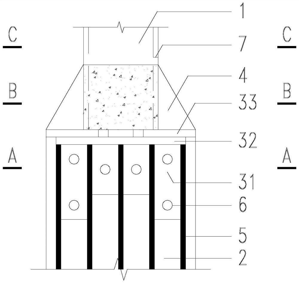
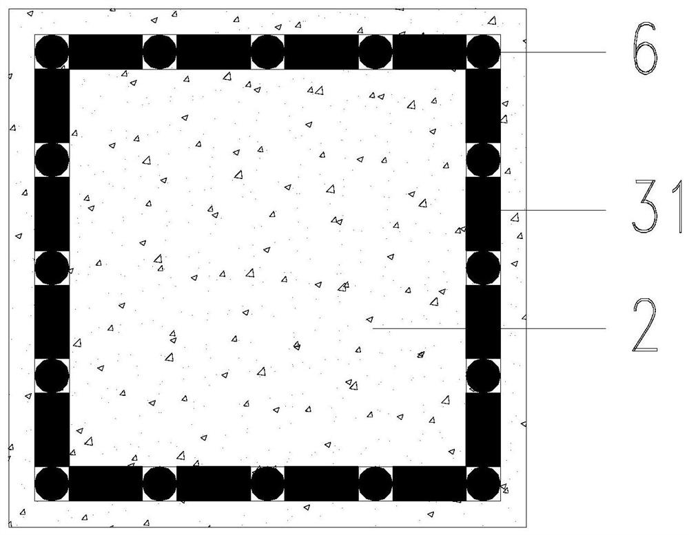
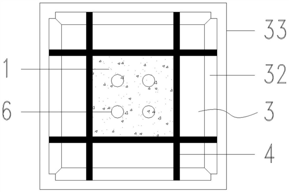
[0042] A rigid connection node between a box-shaped steel column and a concrete column, such as figure 1 , figure 2 , image 3 , Figure 4 , Figure 5 , Figure 6 , Figure 7 , Figure 8 , Figure 9 and Figure 10 , including a box-shaped steel column 1, a concrete column 2 and a steel hoop 3, the concrete column 2 is provided with a concrete column longitudinal bar 5, the steel hoop 3 includes a sealing plate 33 and a rectangular frame plate, the box-shaped steel column 1, the sealing plate 33 and The rectangular frame plates are welded sequentially, and four stiffeners 4 ...


PUM


Abstract

The invention relates to a rigid connection joint between a box-shaped steel column and a concrete column. The rigid connection joint includes the box-shaped steel column, the concrete column and a steel hoop; the concrete column is internally provided with concrete column longitudinal bars; the steel hoop includes a sealing plate and a rectangular frame plate; the box-shaped steel column, the sealing plate and the rectangular frame plate are welded in sequence; each frame of the rectangular frame plate is provided with a plurality of toothed plates in a welded mode; the plurality of toothed plates on each frame are spaced between the concrete column longitudinal bars; the toothed plates are welded to the adjacent concrete column longitudinal bars; the sealing plate is provided with a grout overflow hole located at the bottom of the box-shaped steel column; and the side wall of the box-shaped steel column is provided with an overflow hole. Compared with the prior art, the connection joint has the advantages of high bearing capacity, lateral rigidity and high tensile strength and the like.

Description

technical field [0001] The invention relates to a column connection node, in particular to a rigid connection node between a box-shaped steel column and a concrete column. Background technique [0002] With the continuous development of social economy, people's requirements for the use of buildings are constantly changing, so the original structure needs to be reinforced and transformed. Due to its light weight, high strength, convenient construction, and less wet work, steel structures are widely used in renovation and reinforcement projects. In the reinforcement project, it is often encountered that the building is increased or the roof is increased. At this time, it is necessary to add a steel column to the original concrete column. The conventional method of the structure is to make the connection between the steel column and the concrete column to be hinged. This method is simple and convenient. Fast, but the added steel structure layer has low lateral stiffness, large...

Claims


Application Information

Patent Timeline
IPC IPC(8): E04B1/58E04B1/30
CPCE04B1/185E04B1/30
Inventor 张能伟吴畏朱王炎
Owner TONGJI UNIV ARCHITECTURAL DESIGN INST GRP CO LTD
Learn More