Supercharge Your Innovation With Domain-Expert AI Agents!

Air cooling module mechanical locking design method

An air-cooled module and mechanical locking technology, which is applied to mechanical equipment, friction-clamped detachable fasteners, connecting components, etc. Check and verify the mechanical strength of the cold module to avoid damage to the board and facilitate installation and locking operations

Inactive Publication Date: 2020-11-20
CHENGDU ZHIMINGDA DIGITAL EQUIP
View PDF5 Cites 0 Cited by
  • Summary
  • Abstract
  • Description
  • Claims
  • Application Information

AI Technical Summary

Problems solved by technology

[0002] Air-cooled modules such as VPX and CPCI have no locking mechanism due to structural limitations. Standard air-cooled subracks are assembled from side panels, horizontal connecting rails, and plug-in board guide rails. Air-cooled modules are inserted vertically into subracks along the guide rails. The guide rail of the plug-in board is made of plastic material and the groove width is larger than the thickness of the module flange, so it cannot provide good constraints for the module. The air-cooled module is only fixed on the front horizontal connecting rail by the puller on the panel
When the module is subjected to mechanical strength tests such as vibration, impact, and acceleration with the air-cooled subrack, the module shakes violently in the subrack due to insufficient constraints, and the test conditions such as vibration / shock / acceleration are severely amplified, resulting in the impact on the air-cooled module. The actual conditions of the air-cooled module are much higher than the set conditions, the subracks and modules are easily damaged, and it is difficult to verify the mechanical strength of the air-cooled module

Method used


Image

  • Air cooling module mechanical locking design method
  • Air cooling module mechanical locking design method

Examples


Embodiment Construction

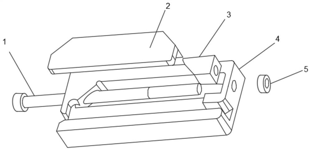
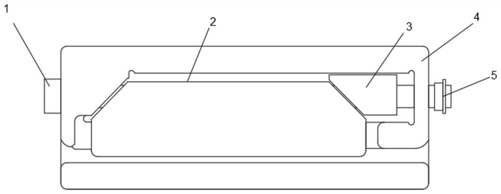
[0020] Such as Figure 1-2 As shown, this specific embodiment adopts the following technical solutions: a mechanical locking design method of an air-cooled module, including an air-cooled sub-box and a locking mechanism, and the locking mechanism is composed of a push screw 1, a clamping block 2, Block 3, locking box 4 and anti-loosening nut 5 consist of the following steps:

[0021] Step 1: First assemble the air-cooled subrack side panels, horizontal connecting rails, and plug-in board guide rails, and insert the air-cooled module into the chassis;

[0022] Step 2: Use a screwdriver to rotate the propulsion screw 1, and the propulsion screw 1 drives the extrusion block 3 to squeeze the clamping block 2 along the horizontal direction of the screw, and the clamping block 2 moves along the inclined plane to press against the air-cooled module.

[0023] Wherein, a small hole is drilled on both sides of the lock box 4, and a push screw 1 is interspersed between the holes on both...


PUM


Abstract

The invention discloses an air cooling module mechanical locking design method. The air cooling module mechanical locking design method comprises a propelling screw rod, a clamping block, an extrusionblock, a locking box and an anti-falling nut, wherein small holes are formed in the two outer sides of the locking box, the propelling screw rod is installed between the holes in the two sides of thelocking box in a penetrating mode, and the propelling screw rod is located at the other end of the locking box and fixed through the anti-falling nut. The air cooling module mechanical locking designmethod has the beneficial effects that the invention opens up a new fixing and locking design idea and method, and provides the novel air cooling module mechanical locking design method by adding a mechanical locking mechanism on an air cooling plug-in board guide rail, the design method is suitable for fixing various air cooling modules, on one hand, board card damage caused by installation andfixation problems in a test can be avoided, on the other hand, installation and locking operation is convenient and fast, and the mechanical locking mechanism can be repeatedly used on different plug-in box clamps.

Description

Technical field: [0001] The invention belongs to the technical field of mechanical locking design methods of air-cooling modules, and in particular relates to a mechanical locking design method of air-cooling modules. Background technique: [0002] Air-cooled modules such as VPX and CPCI have no locking mechanism due to structural limitations. The standard air-cooled subrack is assembled from side panels, horizontal connecting rails, and plug-in board guide rails. The air-cooled module is inserted vertically into the subrack along the guide rails. The guide rail of the plug-in board is made of plastic material and the groove width is larger than the thickness of the module flange, so it cannot provide good constraints for the module. The air-cooled module is fixed on the front horizontal connecting rail only by the puller on the panel. When the module is subjected to mechanical strength tests such as vibration, impact, and acceleration with the air-cooled subrack, the module...

Claims


Application Information

Patent Timeline
Patent Type & Authority Applications(China)
IPC IPC(8): F16B2/14
CPCF16B2/14
Inventor 王芮李鹏飞赵薇娜
Owner CHENGDU ZHIMINGDA DIGITAL EQUIP
Features
  • R&D
  • Intellectual Property
  • Life Sciences
  • Materials
  • Tech Scout
  • Unparalleled Data Quality
  • Higher Quality Content
  • 60% Fewer Hallucinations
Learn More