Solids strainer system for a hydraulic choke

a strainer system and choke technology, applied in the direction of sealing/packing, transportation and packaging, borehole/well accessories, etc., can solve the problems of clogging the screen itself, affecting the flow control of the choke, and causing problems such as particulate matter,

a strainer system and choke technology, applied in the direction of sealing/packing, transportation and packaging, borehole/well accessories, etc., can solve the problems of clogging the screen itself, affecting the flow control of the choke, and causing problems such as particulate matter,

US20050006150A1Inactive Publication Date: 2005-01-13EXPRO AMERICAS

Image

  • Solids strainer system for a hydraulic choke
  • Solids strainer system for a hydraulic choke
  • Solids strainer system for a hydraulic choke

Examples


Embodiment Construction

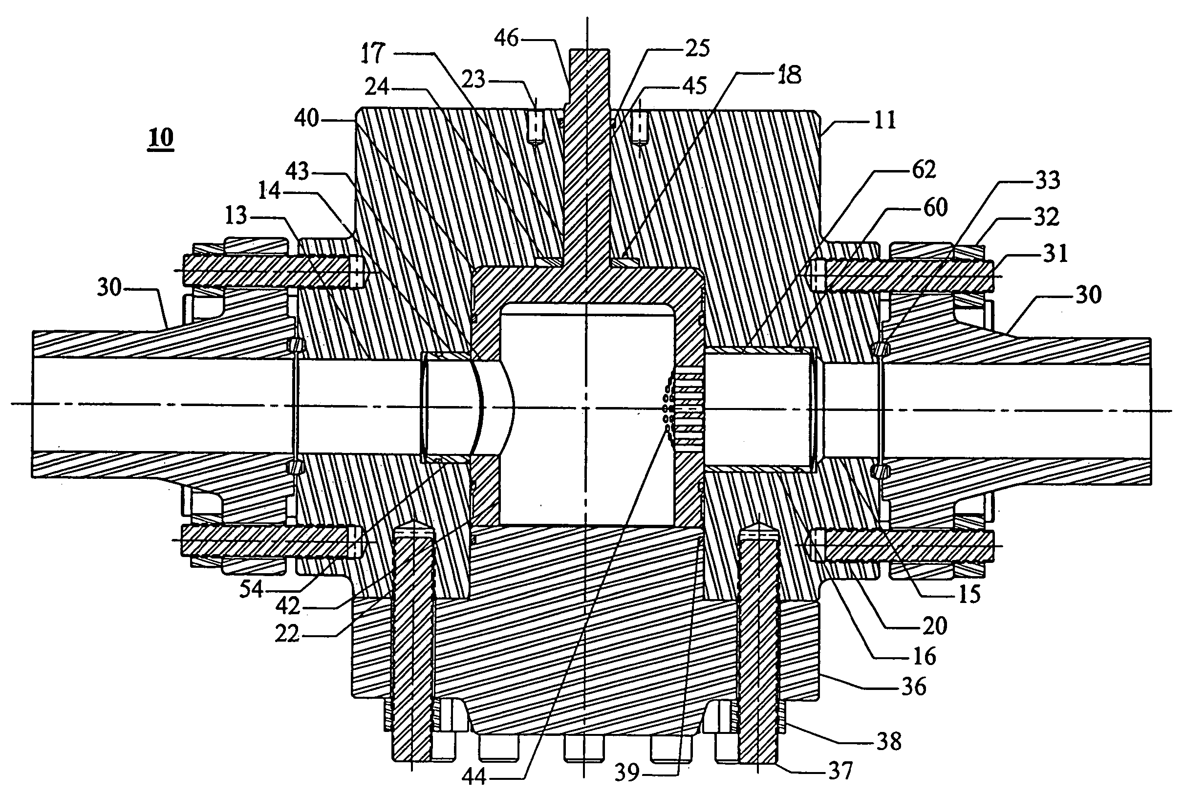
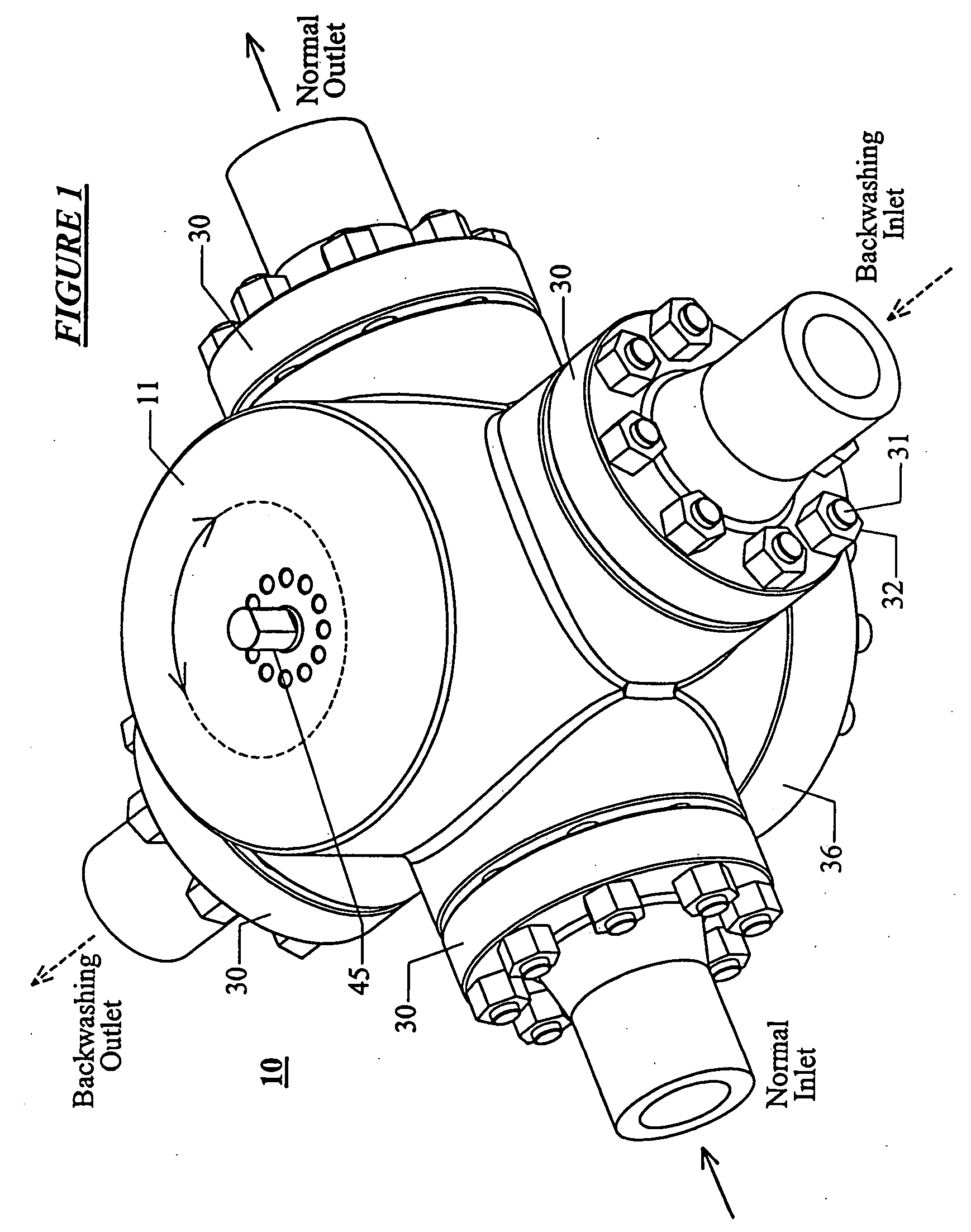
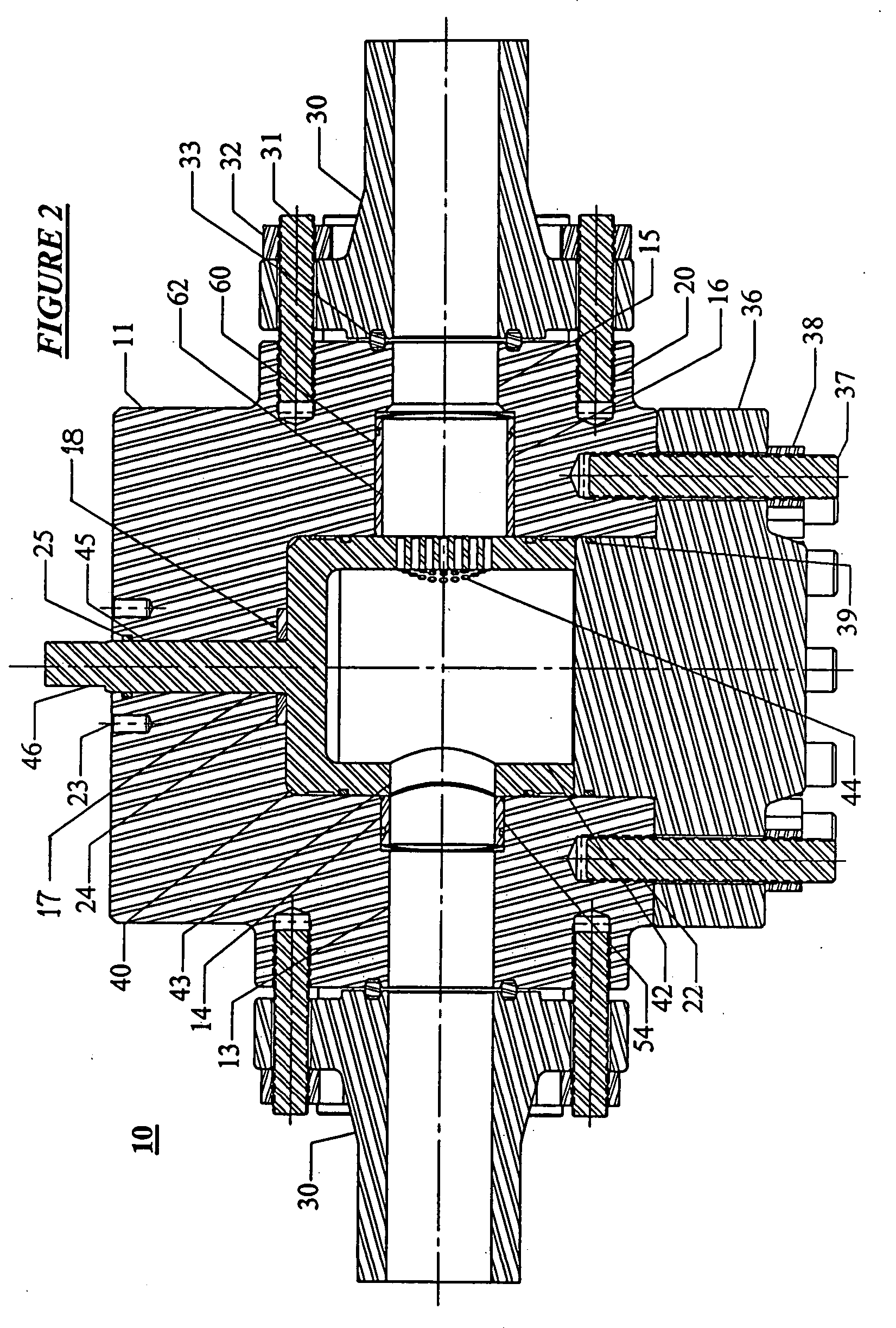
[0035] Referring to FIGS. 1 to 3, the basic strainer assembly 10 is shown in, respectively, oblique, vertical axial cross-sectional, and horizontal cross-sectional views. The major components of the strainer assembly include body 1, valve plug assembly 40, upstream and downstream seals 54 and 60 respectively, and bottom blind flange 36. The components of the strainer assembly 10 are typically made of hardened high strength low alloy steel.

[0036] The strainer basically is a two position, four way cylindrical plug valve with a modified valve plug that provides a straining function. The body 11 of strainer assembly 10 is a right circular cylindrical forging, machined component, or fabrication that has a coaxial right circular cylindrical internal valve cavity 12 and four radial branches positioned at 90° spacings. Each of the radial branches has a right circular cylindrical projected profile and an internal through bore which intersects the cavity 12. Each through flow pair of coaxial...


PUM


Abstract

The invention contemplates a strainer based upon a four-way, two-position rotary cylindrical plug valve having a hollow plug. The normal entry port for the sealing plug of the plug valve is a circular radial hole passing from the exterior of the plug into the interior cavity of the plug. The normal exit port for the sealing plug is a regular array of small holes across from and coaxial with the normal entry hole. The ports for the valve body are in two pairs positioned at 90° from each other, with the axes of the ports lying in the same transverse plane as the ports of the valve plug.

Description

CROSS REFERENCE TO RELATED APPLICATIONS [0001] This application claims priority to pending U.S. Patent Application Ser. No. 60 / 485,187 (Attorney Docket Number PC-P004V, filed Jul. 7, 2004 by Donald Sims, et al. and entitled “Solids Strainer System for a Hydraulic Choke.”BACKGROUND OF THE INVENTION [0002] 1. Field of the Invention [0003] The present invention relates to the drilling and production of fluids from petroleum wells. More particularly, the present invention relates to an apparatus for straining solid particulates from well fluids prior to their passage through a hydraulic choke. [0004] 2. Description of the Related Art [0005] Hydraulic choke devices are commonly used in the oilfield when drilling or treating wells. Herein, the term “hydraulic choke” is taken to refer to the fact that the device is used with a variety of fluids, such as drilling mud, salt water, oil, gas, and other chemicals which may flow into or out from the well. “Hydraulic” does not herein refer to the...

Claims


Application Information

Patent Timeline
13 Jan 2005
Publication
US20050006150A1
IPC
E21B21/06; E21B21/10; E21B34/02; F16K11/085; F16K47/04
CPC
E21B21/06; E21B21/10; F16K47/045; F16K11/0853; E21B34/02; Y10T137/8049; Y10T137/86751; Y10T137/86871
Inventors
SIMS, DONALD GLYNN; TAYLOR, MICHAEL JAMES