Supplier terminal temperature monitoring system

A monitoring system and supplier’s technology, applied in the direction of temperature control using electric methods, can solve the problems of not having temperature, monitoring, and inability to monitor the operating status of supplier terminals in real time, so as to facilitate inspection and maintenance and improve convenience Effect

Inactive Publication Date: 2020-11-20
三亚三力源生态农业有限公司
View PDF5 Cites 1 Cited by
  • Summary
  • Abstract
  • Description
  • Claims
  • Application Information

AI Technical Summary

Problems solved by technology

[0004] The purpose of the present invention is to provide a supplier terminal temperature monitoring system for the deficiencies of the prior art, which solves the problem that the existing supplier terminal does not have the function of monitoring the temperature and cannot monitor the operating status of the supplier terminal in real time

Method used


Image

  • Supplier terminal temperature monitoring system
  • Supplier terminal temperature monitoring system
  • Supplier terminal temperature monitoring system

Examples


Embodiment Construction

[0024] The present invention will be further described below in conjunction with the accompanying drawings and embodiments.

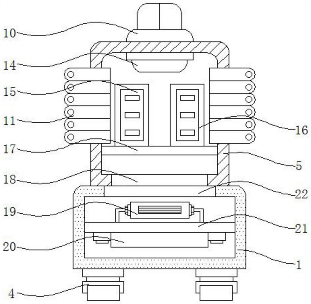
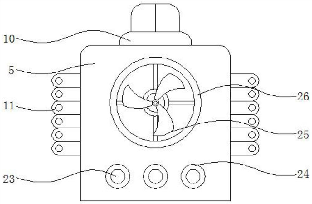
[0025] Please refer to figure 1 , figure 2 , image 3 with Figure 4 ,in, figure 1 A schematic structural diagram of a preferred embodiment of the supplier terminal temperature monitoring system provided by the present invention; figure 2 for figure 1 Cutaway view of the control box shown; image 3 for figure 1 Rear view of control box shown; Figure 4 for figure 1 A diagram of the vendor terminal temperature monitoring system shown. Supplier terminal temperature monitoring system, including support box 1, cooling vent 2, dust-proof net 3, moving wheel 4, control box 5, handle 6, relay 7, box door 8, display screen 9, alarm 10, heat sink 11 , wireless transmission module 12, monitoring terminal 13, lighting lamp 14, server 15, central processing unit 16, installation frame 17, first port 18, refrigerator 19, fan 20, fixed frame 21, second po...


PUM


Abstract

The invention discloses a supplier terminal temperature monitoring system, which comprises a supporting box, a heat dissipation opening, a dust screen, moving wheels, a control box, a handle, a relay,a box door, a display screen, an alarm, a cooling fin, a wireless transmission module, a monitoring terminal, an illuminating lamp, a server, a central processing unit, a mounting frame, a first port, a refrigerator, a fan, a fixing frame, a second port, a threading hole, a protective ring, a cooling fan, a cooling window, a protective circuit, an indicator lamp, a temperature sensor, a control switch and a control power supply. According to the supplier terminal temperature monitoring system, the monitoring terminal is in signal connection with the central processing unit through the wireless transmission module; workers can record the temperature of a supplier terminal in real time, the temperature of the server is sensed in real time through the temperature sensor, the temperature signal is transmitted to the display screen and the central processing unit, and if the temperature value reaches a set early warning value, the central processing unit controls the relay to turn off theserver of the supplier.

Description

technical field [0001] The invention specifically relates to a supplier terminal temperature monitoring system. Background technique [0002] With the development of information technology, more and more data are stored in electronic form to improve the convenience and efficiency of data storage. At the same time, later analysis can be carried out based on these data. The new productivity represented by intelligent tools and the historical process of making them benefit the society, and the productivity that is compatible with intelligent tools, is called information-based productivity. The difference between intelligent production tools and the production tools in the past is that , it is not an isolated and scattered thing, but a large-scale, top-down and organized information network system. This networked production tool will change people's production methods, work methods, learning methods, The way of communication, way of life and way of thinking will cause extremely...

Claims


Application Information

Patent Timeline
Patent Type & Authority Applications(China)
IPC IPC(8): G05D23/19
CPCG05D23/19
Inventor 瞿长伍
Owner 三亚三力源生态农业有限公司
Why Eureka
Try Eureka