
Computer hardware interface with protection function

A technology for computer hardware and protection functions, applied in the direction of computer peripheral equipment connectors, parts of connecting devices, connections, etc., can solve the problems of reducing the service life of the interface, corrosion of the interface, and inability to transmit, so as to prolong the service life and ensure normal operation. Transmission, friction reduction effect

Inactive Publication Date: 2020-11-20
祁阳市育昊电子商务有限公司
View PDF8 Cites 2 Cited by
  • Summary
  • Abstract
  • Description
  • Claims
  • Application Information

AI Technical Summary

Problems solved by technology

[0003] The hardware interface on the existing computer mainframe usually inserts the hardware plug directly into the hardware interface, so that the interface and the chip of the plug are directly bonded. When the hardware plug is inserted and connected, the plug chip will generate friction on the inner wall of the interface, which will cause friction on the plug. The chip has certain damage, and it is easy to damage the chip after long-term use. Secondly, the interface is generally exposed, and exposed to the air for a long time, the interface is easy to fall into a large amount of dust, debris and even water. These The substance will corrode the interface to a certain extent, which greatly reduces the service life of the interface, thereby affecting the transmission of data, and even the phenomenon that it cannot be transmitted. Therefore, those skilled in the art provide a computer hardware interface with protective function , to solve the problems raised in the above background technology

Method used


Image

  • Computer hardware interface with protection function
  • Computer hardware interface with protection function
  • Computer hardware interface with protection function

Examples


Embodiment Construction

[0023] The following will clearly and completely describe the technical solutions in the embodiments of the present invention with reference to the accompanying drawings in the embodiments of the present invention. Obviously, the described embodiments are only some, not all, embodiments of the present invention. Based on the embodiments of the present invention, all other embodiments obtained by persons of ordinary skill in the art without making creative efforts belong to the protection scope of the present invention.

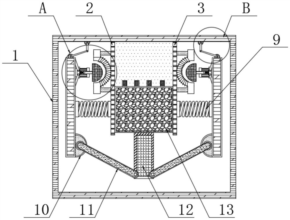
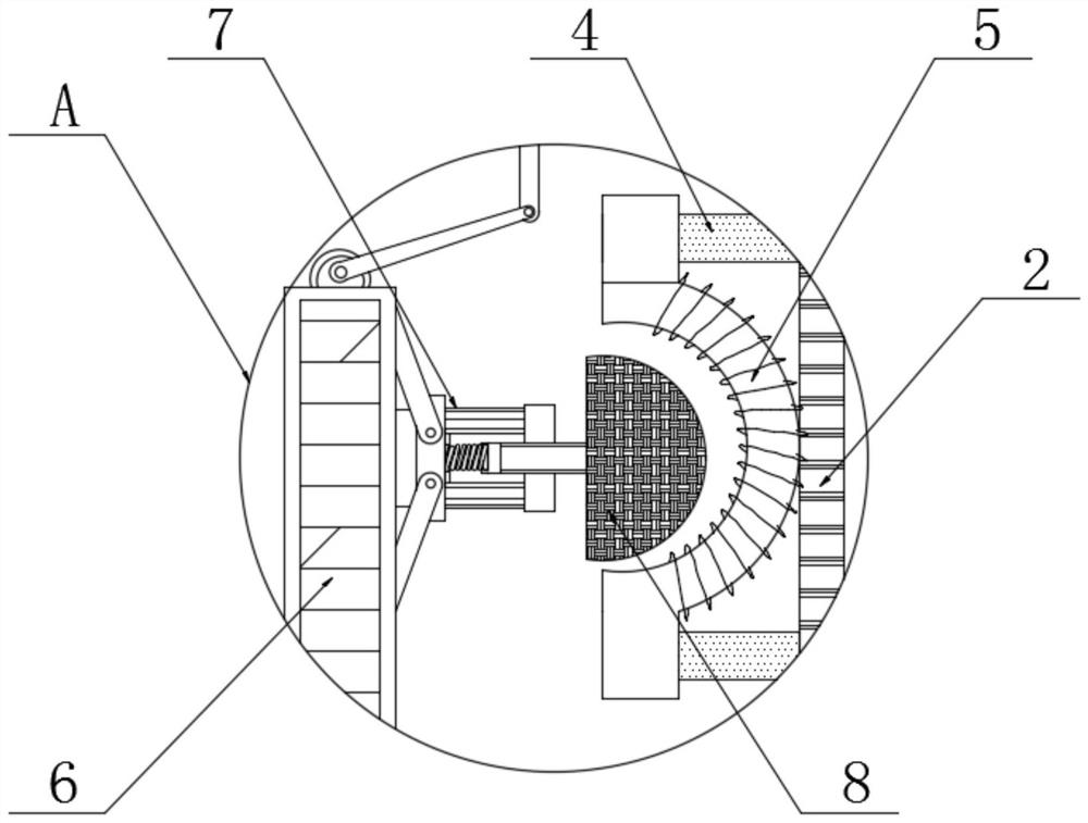
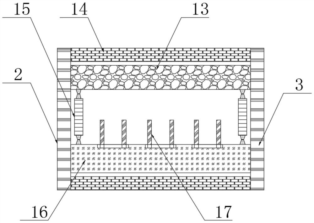
[0024] see Figure 1-6 , a computer hardware interface with a protective function, comprising a host body 1, the inner wall of the host body 1 is fixedly connected with a first conductive plate 2, and the inner wall of the host body 1 is fixedly connected with a second conductive plate 2 on the right side of the first conductive plate 2 The conductive plate 3, the length of the first conductive plate 2 and the second conductive plate 3 are equal, the first con...


PUM


Abstract

The invention relates to the technical field of computer hardware, in particular to a computer hardware interface with a protection function. The inner wall of a host body is fixedly connected with afirst conductive plate; a second conductive plate is fixedly connected to the inner wall of the host body and located on the right side of the first conductive plate; the outer surface of the first conductive plate is fixedly connected with a metal guide plate; one end of the metal guide plate is fixedly connected with an electromagnet; one end of the outer connecting sleeve is fixedly connected with an arc-shaped iron block; a hinged support is fixedly connected to the outer surface of the supporting plate and located below the first spring; the outer surface of the hinged support is movablyconnected with an adjusting plate; the bottom end of the adjusting plate is movably connected with a push plate; a limiting block is fixedly connected to the top end of the push plate, an electromagnet is used for attracting an arc-shaped iron block to drive the limiting block to move up and down, automatic plugging of the limiting block on the interface is achieved, the interior of the interfaceis prevented from being damaged by external substances when hardware is not inserted, and then the service life of the host hardware interface is prolonged.

Description

technical field [0001] The invention relates to the technical field of computer hardware, in particular to a computer hardware interface with protection function. Background technique [0002] A computer is composed of a variety of hardware. The hardware interface refers to the connection method between two hardware devices. The hardware interface includes both the physical interface and the logical data transmission protocol. The computers commonly used in daily life are Configured with different hardware interfaces, it is convenient for people to use for data transmission. [0003] The hardware interface on the existing computer mainframe usually inserts the hardware plug directly into the hardware interface, so that the interface and the chip of the plug are directly bonded. When the hardware plug is inserted and connected, the plug chip will generate friction on the inner wall of the interface. The chip has certain damage, and it is easy to damage the chip after long-te...

Claims


Application Information

Patent Timeline
IPC IPC(8): H01R13/52H01R13/10H01R13/502
CPCH01R13/10H01R13/502H01R13/52H01R2201/06
Inventor 吴国强
Owner 祁阳市育昊电子商务有限公司
Learn More