
Multifunctional cable trench with high safety performance

A technology of safety performance and cable trench, applied in the field of multi-functional cable trench, can solve problems such as insufficient cable trench space, occupation of equipment foundation, difficulty in cable laying, etc., achieve clear and smooth cable direction, reduce project cost, and save materials.

Pending Publication Date: 2020-11-20
河源联禾电力规划设计有限公司
View PDF0 Cites 0 Cited by
  • Summary
  • Abstract
  • Description
  • Claims
  • Application Information

AI Technical Summary

Problems solved by technology

[0006] Existing problems: In outdoor sites and indoor high-voltage chambers, usually control cables and power cables need to be laid on both sides of the cable trench, resulting in power cables needing to pass through the control cable trench, and control cables also need to pass through the power cable trench. There are many internal pipes, which is not conducive to fire prevention, and also brings difficulties to cable laying
[0007] In the outdoor field, the main control cable trench is usually set between the circuit breaker and the current transformer. The distance between the circuit breaker and the current transformer is 2.5 meters. The equipment foundation occupies a large space. There is not enough space for two cable trenches, so it is necessary to The power cable trench and the control cable trench are set separately, so that the power cable trench and every interval branch cable trench need to cross, and there are many buried pipes, making cable laying difficult
[0008] The technical requirements also require that the double-circuit low-voltage power cables should be separated by fire protection, and it is still necessary to install a fire-proof box in the low-voltage power cable trench, which will increase the investment a lot

Method used


Image

  • Multifunctional cable trench with high safety performance
  • Multifunctional cable trench with high safety performance
  • Multifunctional cable trench with high safety performance

Examples


Embodiment 1

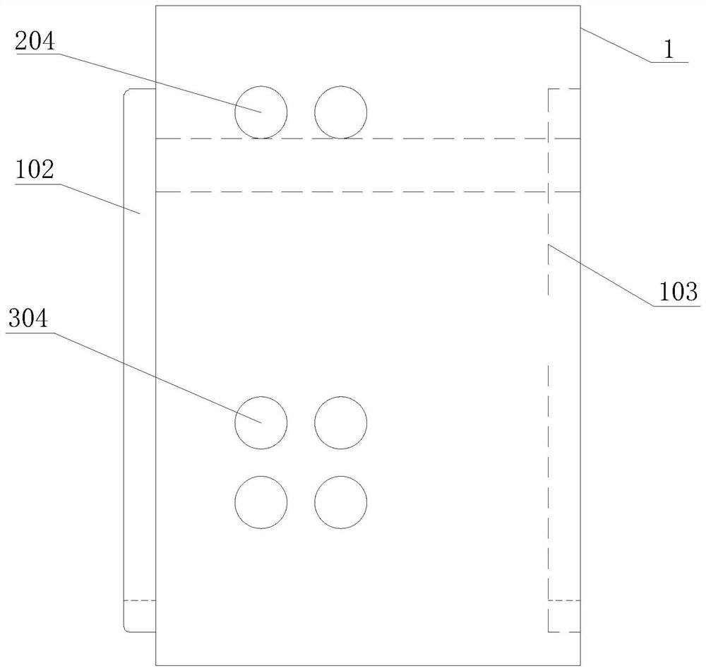
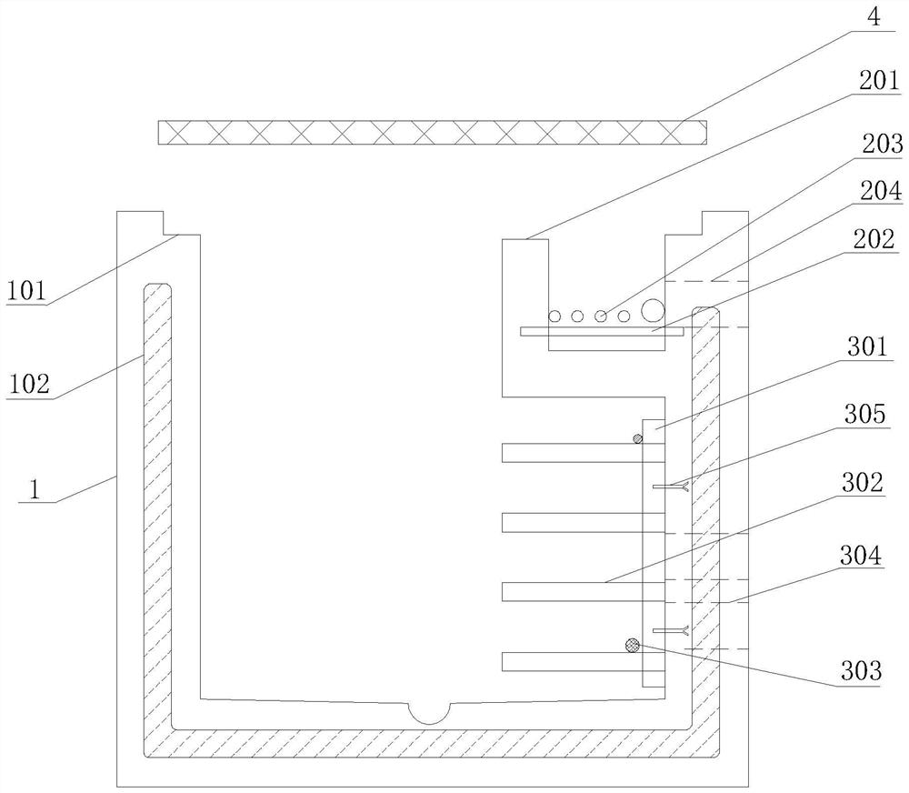
[0031] see Figure 1-2 , in the embodiment of the present invention: a multifunctional cable trench with high safety performance, including a cable trench body 1, the interior of the cable trench body 1 is divided into a power cable wiring area 2 and a control cable wiring area 3, and the power cable wiring area 2 and The control cable wiring area 3 is distributed up and down on the side wall of the cable trench body 1; wherein, according to construction requirements, a group of power cable wiring areas 2 and a group of control cables are distributed up and down on the side wall of the cable trench body 1 The wiring area 3 forms a single control cable single force cable trench structure.

[0032] In the above embodiment, the power cable wiring area 2 is composed of angle steel 201 and round steel 202. The angle steel 201 is integrally embedded above the inner wall of the cable trench body 1, and the opening is upward. The bottom of the angle steel 201 and the cable trench body...

Embodiment 2

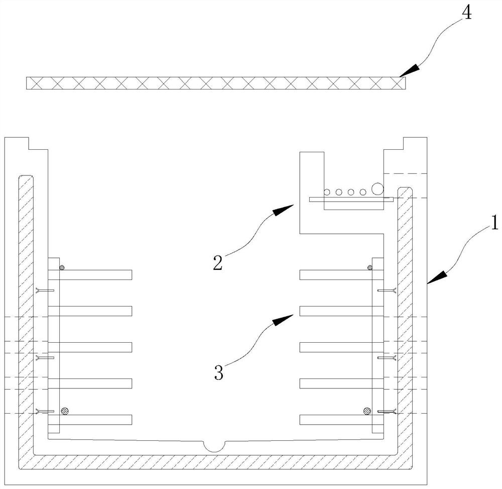
[0038] see image 3, in the embodiment of the present invention: a multifunctional cable trench with high safety performance, including a cable trench body 1, the interior of the cable trench body 1 is divided into a power cable wiring area 2 and a control cable wiring area 3, and the power cable wiring area 2 and The control cable wiring area 3 is distributed up and down on the side wall of the cable trench body 1; wherein, according to construction requirements, a group of power cable wiring areas 2 and a group of control cables are distributed up and down on the side wall of the cable trench body 1 Wiring area 3, and a set of control cable wiring area 3 is provided on the other side wall of the cable trench body 1 to form a cable trench structure with double control cables and single force cables.

[0039] In the above embodiment, the power cable wiring area 2 is composed of angle steel 201 and round steel 202. The angle steel 201 is integrally embedded above the inner wall...

Embodiment 3

[0045] see Figure 4 , in the embodiment of the present invention: a multifunctional cable trench with high safety performance, including a cable trench body 1, the interior of the cable trench body 1 is divided into a power cable wiring area 2 and a control cable wiring area 3, and the power cable wiring area 2 and The control cable wiring area 3 is distributed up and down on the side wall of the cable trench body 1; wherein, according to construction requirements, a group of power cable wiring areas 2 and a group of control cable wiring areas are distributed up and down on both sides of the cable trench body 1. The cable routing area 3 forms a cable trench structure with dual control cables and dual force cables.

[0046] In the above embodiment, the power cable wiring area 2 is composed of angle steel 201 and round steel 202. The angle steel 201 is integrally embedded above the inner wall of the cable trench body 1, and the opening is upward. The bottom of the angle steel 2...


PUM


Abstract

The invention discloses a multifunctional cable trench with high safety performance, which comprises a cable trench body, and is characterized in that the interior of the cable trench body is dividedinto a power cable wiring area and a control cable wiring area, and the power cable wiring area and the control cable wiring area are distributed on the side wall of the cable trench body in an up-and-down space; according to construction requirements, a single-control-cable single-force-cable cable trench structure, a double-control-cable single-force-cable cable trench structure and a double-control-cable double-force-cable cable trench structure can be formed through division of the power cable wiring area and the control cable wiring area. On the basis of a traditional prefabricated cabletrench, a low-voltage power cable subarea is additionally arranged; according to the number of the control cables and the power cables and the trend characteristics of the cables, different types of single-control-cable single-force cables, double-control-cable single-force cables, double-control-cable double-force cables and the like can be flexibly selected, so that the requirements of differentuse scenes are met.

Description

technical field [0001] The invention relates to the technical field of cable trenches, in particular to a multifunctional cable trench with high safety performance. Background technique [0002] In recent years, there have been many electrical fire accidents in the domestic power system, exposing many problems in fire protection design, transformation, acceptance and operation and maintenance. In order to further promote the lean prevention and control of electrical fires, avoid the occurrence or expansion of electrical fire accidents, and improve the level of electrical fire prevention and control in substations, China Southern Power Grid has successively issued the "Special Anti-Accident Measures for Preventing Major Electrical Fires and Equipment Failures", "China Southern Power Grid Corporation Documents such as the Special Action Plan for Improving the Health Level of AC and DC Power Supply Equipment for Substations, and the Technical Requirements for Electrical Fire Pr...

Claims


Application Information

Patent Timeline
Patent Type & Authority Applications(China)
IPC IPC(8): H02G9/02H02G9/06
CPCH02G9/025H02G9/06
Inventor 廖建辉李琪周海辉龚小秋刘小泽张祺黄志雄
Owner 河源联禾电力规划设计有限公司
Learn More