Amplitude-phase control method for power grid dominant voltage source converter

A voltage source converter, amplitude-phase control technology, applied in electrical components, circuit devices, AC network circuits, etc., can solve problems such as difficulty in suppressing converter power oscillations

Active Publication Date: 2020-11-20
INST OF ELECTRICAL ENG CHINESE ACAD OF SCI
View PDF15 Cites 1 Cited by
  • Summary
  • Abstract
  • Description
  • Claims
  • Application Information

AI Technical Summary

Problems solved by technology

However, this scheme does not start from revealing the power oscillation mechanism, and it is difficult to suppress the power oscillation between the converter and the traditional synchronous generator

Method used


Image

  • Amplitude-phase control method for power grid dominant voltage source converter
  • Amplitude-phase control method for power grid dominant voltage source converter
  • Amplitude-phase control method for power grid dominant voltage source converter

Examples


Embodiment Construction

[0071] The present invention will be further described below in conjunction with the accompanying drawings, specific implementation methods and examples.

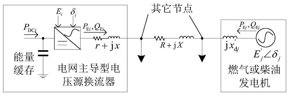
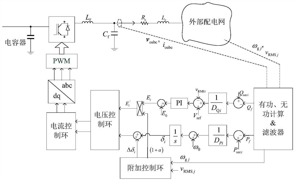
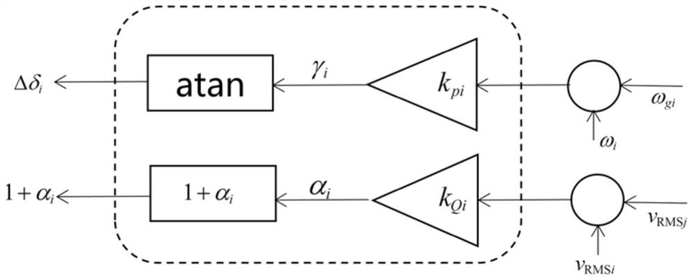
[0072] Such as figure 2 As shown, the present invention changes the instantaneous output electromagnetic power of the converter by controlling the terminal voltage phase of the grid-dominated converter, thereby suppressing system power oscillation. First, based on the dynamic differential equations of traditional synchronous generators and grid-dominated converters and the algebraic equations of the microgrid, the dynamic equation of the micro-increase rate of the whole system is established; based on the dynamic equation of the micro-increase rate, the Lyapunov stability of the whole system is evaluated , and design the additional controller of the grid-dominated converter; finally, by collecting the angular frequency of the traditional synchronous generator and the grid-dominated converter, the instantaneous output elect...


PUM


Abstract

The invention discloses an amplitude-phase control method for a power grid dominant voltage source converter. Firstly, a multi-type power supply dynamic differential and microgrid algebraic equation is established; a compensation control loop of a power grid dominant voltage source converter is provided. Secondly, an island alternating-current microgrid whole-system dynamic micro-increment rate model containing multiple types of power supplies and a converter compensation control loop is established, and compensation control loop parameters are designed and amplitude-phase variables are adjusted on the basis of a transient energy function of the micro-increment rate model so as to guarantee dynamic stability of the whole system, thereby suppressing a power oscillation phenomenon among themultiple types of power supplies.

Description

technical field [0001] The invention relates to a control method of a grid-dominated voltage source converter. Background technique [0002] At present, distributed wind power and photovoltaic power generation, DC loads and energy storage devices are generally connected to AC microgrids through voltage source converters. The traditional voltage source converter tracks the grid frequency through a phase-locked loop. Compared with the power angle characteristics of conventional synchronous generators such as gas turbines, it shows characteristics such as constant current source access, maximum power input or output, and no spinning reserve. As more current source converters replace conventional synchronous generators, that is, to increase the proportion of new energy power generation and reduce the start-up of synchronous generators, the overall inertia of the system and the active rotating reserve capacity will decrease, and the power supply’s ability to support the grid volt...

Claims


Application Information

Patent Timeline
Patent Type & Authority Applications(China)
IPC IPC(8): H02J3/24H02J3/40
CPCH02J3/241H02J3/40H02J2203/20
Inventor 叶华刘垚裴玮孔力
Owner INST OF ELECTRICAL ENG CHINESE ACAD OF SCI
Why Eureka
Try Eureka