LED driving circuit and control method thereof, and LED driving device

A LED drive and bypass control technology, applied in the field of power electronics, can solve the problem of no leakage protection

Pending Publication Date: 2020-11-20
HANGZHOU SILAN MICROELECTRONICS
View PDF4 Cites 0 Cited by
  • Summary
  • Abstract
  • Description
  • Claims
  • Application Information

AI Technical Summary

Problems solved by technology

Since the LED drive circuit of the fluorescent lamp with leakage protection function has only two input terminals, that is, the neutral line and live line input terminals, there are no other ports for dimming
[0005] In addition, although the existing dimming technology can solve the dimming of the input at both ends of the fluorescent lamp, it has no leakage protection function.

Method used


Image

  • LED driving circuit and control method thereof, and LED driving device
  • LED driving circuit and control method thereof, and LED driving device
  • LED driving circuit and control method thereof, and LED driving device

Examples


Embodiment Construction

[0068] Various embodiments of the invention will be described in more detail below with reference to the accompanying drawings. In the various drawings, the same elements are denoted by the same or similar reference numerals. For the sake of clarity, various parts in the drawings have not been drawn to scale.

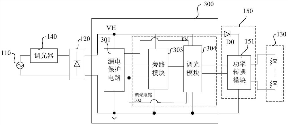
[0069] image 3 A schematic circuit diagram of the LED driving device according to the first embodiment of the present invention is shown. The LED driving device includes a dimmer 140 , a rectifier bridge 120 , an LED driving circuit 300 and a power conversion circuit 150 . Wherein, the dimmer 140 obtains an AC input voltage from an external AC power source 110 (ie, a power supply), and outputs an AC input voltage with dimming data based on a dimming action. The rectifier bridge 120 rectifies the AC input voltage with dimming data to output a DC bus voltage VH with dimming data. The LED driving circuit 300 performs dimming according to the DC bus voltage VH with dim...


PUM


Abstract

The invention discloses an LED driving circuit. The circuit comprises an electric leakage protection circuit, and a dimming circuit, wherein the electric leakage protection circuit detects whether anelectric leakage phenomenon exists or not and generates an electric leakage control signal; and the dimming circuit is connected with the electric leakage protection circuit and is used for receivingthe electric leakage control signal, dimming is performed according to the electric leakage control signal by the dimming circuit when the electric leakage phenomenon does not exist, and dimming is stopped according to the electric leakage control signal by the dimming circuit when the electric leakage phenomenon exists. According to the LED driving circuit provided by the embodiment of the invention, when electric leakage detection is carried out and the electric leakage phenomenon exists, the electric leakage protection circuit makes a bypass module be intermittently conducted to carry out electric leakage detection and protection, and when the electric leakage phenomenon does not exist, the dimming module makes the bypass module be conducted or cut off to carry out dimming data and power transmission so as to realize dimming.

Description

technical field [0001] The present application relates to the related fields of power electronics, and in particular, relates to an LED driving circuit, a control method thereof, and an LED driving device. Background technique [0002] LED lamps are used more and more in the field of lighting, such as classrooms, shopping malls, office buildings, etc., including fluorescent lamps. During installation, one end is usually installed first, and then the other end is installed. If the operator accidentally touches the electrode on the other end with his hands or other parts of the body when installing one end, the human body and the power grid will form a loop, which will cause electric shock. At present, this problem is solved by adding leakage protection circuit. [0003] An existing LED drive circuit 100 with a leakage protection function includes a leakage protection circuit 101 and a power conversion circuit 102, such as figure 1 shown. The LED driving circuit 100 obtains...

Claims


Application Information

Patent Timeline
IPC IPC(8): H05B45/325H05B45/345H05B45/375H05B45/38H05B45/50
CPCH05B45/325H05B45/345H05B45/375H05B45/38H05B45/50Y02B20/30
Inventor 叶美盼林星宇
Owner HANGZHOU SILAN MICROELECTRONICS
Why Eureka
Try Eureka