Circuit board and manufacturing method thereof

A technology for circuit board fabrication and conductive circuit layer, applied in printed circuit manufacturing, printed circuit, printed circuit components, etc., can solve problems such as the influence of conductive bumps, uneven ink thickness, and the inability of dry film to completely cover the conductive bumps. , to achieve the effect of easy production

Inactive Publication Date: 2020-11-20
AVARY HLDG (SHENZHEN) CO LTD +1
View PDF6 Cites 0 Cited by
  • Summary
  • Abstract
  • Description
  • Claims
  • Application Information

AI Technical Summary

Problems solved by technology

However, the height of the conductive bumps will affect other processes. For example, in the process of circuit fabrication, the dry film cannot completely cover the conductive bumps, so that the conductive bumps are partially etched during etching. In addition, when forming the solder mask , the conductive bumps may break the printing screen or make the ink thickness uneven

Method used


Image

  • Circuit board and manufacturing method thereof
  • Circuit board and manufacturing method thereof
  • Circuit board and manufacturing method thereof

Examples


Embodiment Construction

[0035] The following will clearly and completely describe the technical solutions in the embodiments of the present invention with reference to the accompanying drawings in the embodiments of the present invention. Obviously, the described embodiments are only some, not all, embodiments of the present invention. Based on the embodiments of the present invention, all other embodiments obtained by persons of ordinary skill in the art without making creative efforts belong to the protection scope of the present invention.

[0036] Unless otherwise defined, all technical and scientific terms used herein have the same meaning as commonly understood by one of ordinary skill in the technical field of the invention. The terms used herein in the description of the present invention are for the purpose of describing specific embodiments only, and are not intended to limit the present invention.

[0037] Some embodiments of the present invention will be described in detail below in conju...


PUM


Abstract

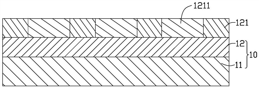
The invention provides a circuit board manufacturing method, which comprises the following steps: providing a copper-clad unit, wherein the copper-clad unit comprises a base layer and at least one copper foil layer located on the base layer; manufacturing the copper foil layer to form a conductive circuit layer, wherein the conductive circuit layer comprises at least one connecting pad; forming asolder mask layer on the conductive circuit layer, wherein the solder mask layer comprises at least one window, and at least one connecting pad is exposed out of at least one window; and forming a conductive bump on at least one of the connection pads. The invention also provides a circuit board.

Description

technical field [0001] The invention relates to a circuit board and a manufacturing method thereof. Background technique [0002] When a circuit board is connected to another circuit board or component through a hot-bar welding process, in order to align the two connection pads to be soldered, it is usually necessary to form conductive bumps on the connection pads. The conductive bump needs to be higher than the entire circuit board, and generally more than 30 microns higher than the circuit board. However, the height of the conductive bump will affect other processes. For example, in the process of circuit making, the dry film cannot completely cover the conductive bump, so that the conductive bump is partially etched during etching. In addition, when forming the solder mask layer , the conductive bumps may break the printing screen or make the ink thickness uneven. Contents of the invention [0003] In view of this, it is necessary to provide a circuit board and a manu...

Claims


Application Information

Patent Timeline
Patent Type & Authority Applications(China)
IPC IPC(8): H05K3/28H05K1/02
CPCH05K1/02H05K3/282
Inventor 何四红
Owner AVARY HLDG (SHENZHEN) CO LTD
Why Eureka
Try Eureka