filter device

A filter device and filter unit technology, which is applied in the direction of dispersed particle filtration, separation method, and dispersed particle separation, etc. It can solve the problems of being unable to judge the filter unit, not knowing when to replace the filter unit, and being unable to prevent and maintain

Active Publication Date: 2022-03-11
CKD
View PDF21 Cites 0 Cited by
  • Summary
  • Abstract
  • Description
  • Claims
  • Application Information

AI Technical Summary

Problems solved by technology

[0003] However, in the device of Japanese Patent Application Laid-Open No. 2010-101702, if the difference between the pressure of the compressed air before passing through the filter and the pressure of the compressed air after passing through the filter is not large enough, it cannot be judged that the filter is present. blocked state
Therefore, there is a problem that preventive maintenance cannot be performed without knowing the optimum replacement timing of the filter unit.

Method used


Image

  • filter device
  • filter device
  • filter device

Examples


Embodiment Construction

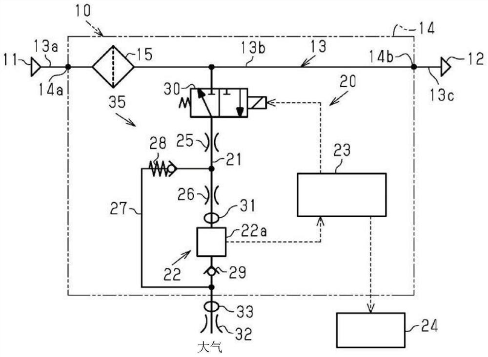
[0020] Below, according to figure 1 The first embodiment of the actual filtering device will be described.

[0021] Such as figure 1 As shown, the filter device 10 is provided in a supply flow path 13 that supplies compressed air from an air supply source 11 to a pneumatic machine 12 . The pneumatic machine 12 is driven by compressed air supplied from the air supply source 11 through the supply flow path 13 . The supply channel 13 is constituted by, for example, piping or the like.

[0022] The filter device 10 has a body 14 . The main body 14 has a supply hole 14a and a discharge hole 14b. The supply channel 13 has a first channel 13a, a second channel 13b, and a third channel 13c. The first flow path 13 a connects the air supply source 11 and the supply hole 14 a outside the main body 14 . The second flow path 13b connects the supply hole 14a and the discharge hole 14b inside the main body 14 . The third flow path 13c connects the discharge hole 14b and the pneumatic ...


PUM


Abstract

The filter device includes a filter unit and a particle detector. The particle detector is installed in a supply channel that supplies compressed air from an air supply source to the pneumatic equipment, and removes particles contained in the compressed air flowing through the supply channel. The particle detector has a detection channel, an optical sensor, and a flow rate adjustment unit. The detection flow path is branched from a part of the supply flow path on the downstream side in the flow direction of the compressed air from the filter unit, and is connected to the atmosphere. The optical sensor detects particles contained in the compressed air flowing through the detection channel. The flow velocity adjustment unit adjusts the flow velocity of the compressed air flowing toward the optical sensor through the detection flow path to a predetermined flow velocity regardless of the flow velocity of the compressed air flowing through the supply flow path.

Description

technical field [0001] The invention relates to a filter device. Background technique [0002] For example, pneumatic machines used in factories and the like are driven by compressed air supplied from an air supply source through a supply flow path. Generally, a filter device having a filter unit (filter unit) for removing particles contained in compressed air flowing through the supply flow path is provided in the supply flow path before the compressed air is supplied to the pneumatic equipment. However, as the filter continues to be used, it will gradually become clogged, reducing the ability to remove particles. Regarding this point, for example, the device described in JP 2010-101702 A can detect the difference between the pressure of the compressed air before passing through the filter and the pressure of the compressed air after passing through the filter. In addition, the larger the pressure difference, the more it can be judged that the filter unit is in a clogged ...

Claims


Application Information

Patent Timeline
Patent Type & Authority Patents(China)
IPC IPC(8): B01D46/44B01D46/46B01D46/00B01D46/42
CPCB01D46/44B01D46/442B01D46/446B01D46/46B01D46/4236B01D46/42B01D46/0041
Inventor 伊藤新治林清信
Owner CKD
Why Eureka
Try Eureka