Leak detection method and associated valve and fuel system

a leak detection and leak detection technology, applied in the direction of valve operating means/release devices, machines/engines, instruments, etc., can solve the problem of high detection method cost, and achieve the effect of continuous and accurate leak detection, not burdening neither cost nor efficiency of the resul

Inactive Publication Date: 2011-03-15
PLASTIC OMNIUM ADVANCED INNOVATION & RES SA
View PDF40 Cites 6 Cited by
  • Summary
  • Abstract
  • Description
  • Claims
  • Application Information

AI Technical Summary

Benefits of technology

[0011]To avoid the drawbacks of prior art, the applicant's invention relates to a system using existing technology, i.e. current components of the fuel system with no need for any additional sensors, or devices. It does not require any additional devices, volumes, or changes to the normal day to day operation of the vehicles. With the help of an intelligent fuel system or IFS (i.e. a fuel system comprising a fuel system control unit (FSCU) and data network connection), the present invention allows a continuous and accurate detection of leaks (even small leaks) in a fuel system based on the measurement of pressure differentials, which does not burden neither the cost nor the efficiency of the result since the IFS uses only existing sensors to perform the leak detection.

Problems solved by technology

The cost of the detection method is high since additional processing devices are to be implemented.
Additionally, known prior art methods for leak detection are generally carried out when the engine has been turned off.

Method used


Image

  • Leak detection method and associated valve and fuel system
  • Leak detection method and associated valve and fuel system
  • Leak detection method and associated valve and fuel system

Examples


Embodiment Construction

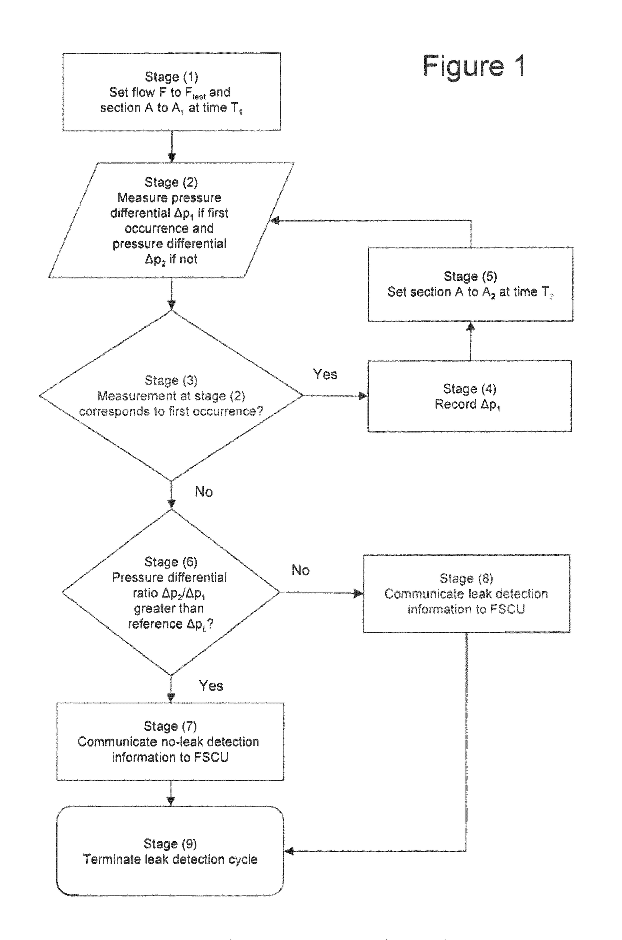
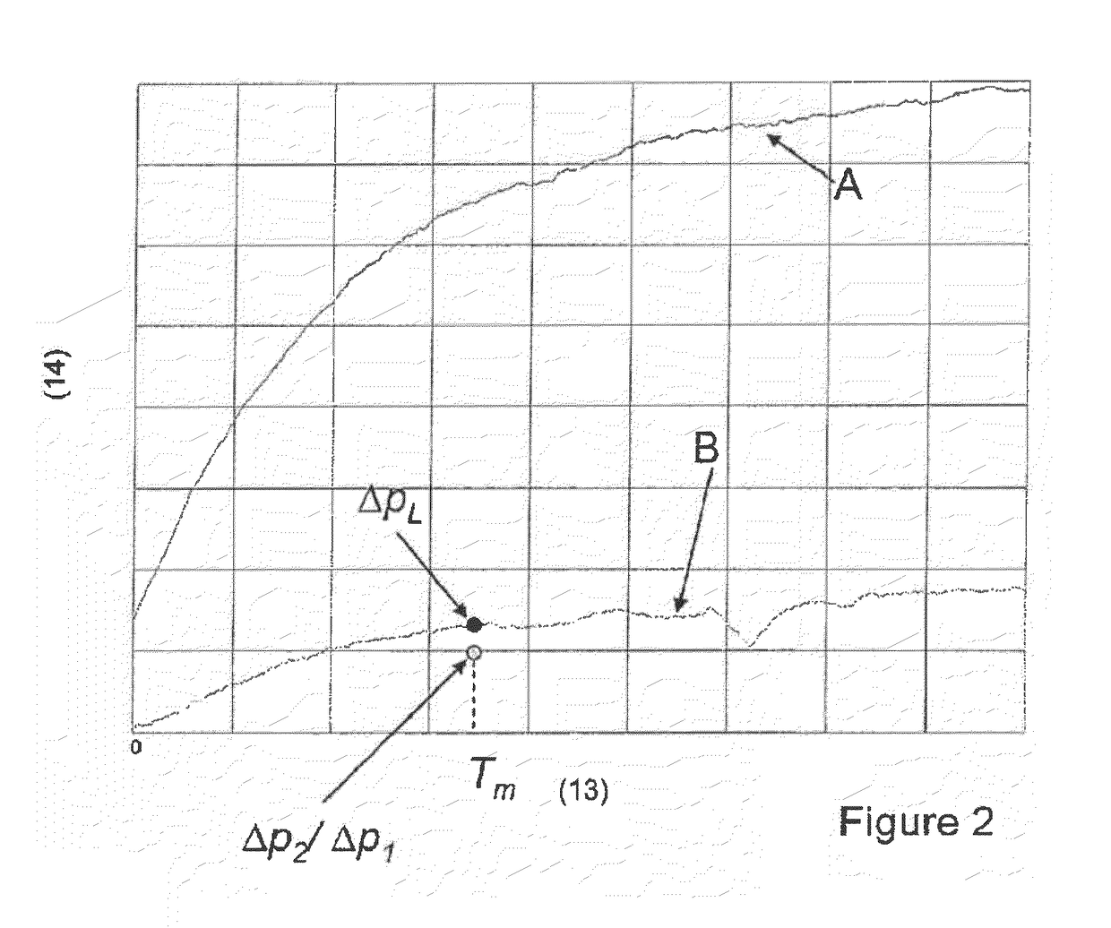
[0018]To this effect the present invention relates to a method of detecting a leak in a fuel system comprising a fuel tank and an orifice with a controlled section between the tank and the atmosphere, according to which:[0019]a) the controlled section is set to a value A1 at a time T1 and a pressure differential Δp1 between the inside of said fuel tank and the atmosphere is measured at least after an interval of time ΔT from T1, for a constant fuel flow F out of said fuel tank;[0020]b) the controlled section is set to a value A2 at a time T2 and a pressure differential Δp2 between the inside of said fuel tank and the atmosphere is measured at least after the same interval of time ΔT from T2, for the same constant fuel flow F;[0021]c) a ratio of said pressure differentials Δp1 and Δp2 is computed and is compared to a reference pressure differential ratio ΔpL obtained with the same fuel system but comprising a calibrated leak.

[0022]According to the invention, the fuel system comprises...


PUM


Abstract

Method of detecting a leak in a fuel system comprising a fuel tank and an orifice with a controlled section between the tank and the atmosphere, according to whicha) the controlled section is set to a value Al at a time T1 and a pressure differential Δp1 between the inside of the tank and the atmosphere is measured at least after an interval of time ΔT from T1, for a constant fuel flow out of the tank;b) the controlled section is set to a value A2 at a time T2 and a pressure differential Δp2 between the inside of the tank and the atmosphere is measured at least after the same interval of time ΔT from T2, for the same constant fuel flow;c) a ratio of the pressure differentials Δp1 and Δp2 is computed and is compared to a reference pressure differential ratio ΔpL obtained with the same fuel system but comprising a calibrated leak.

Description

CROSS-REFERENCE TO RELATED APPLICATIONS[0001]The present application is a U.S. national stage application under 35 U.S.C. §371 of International Application No. PCT / EP2007 / 051056, filed Feb. 5, 2007, which claims the benefit of U.S. provisional application Ser. No. 60 / 765,741 filed Feb. 7, 2006, of European patent application serial No. 06101356.1 filed Feb. 2, 2006, and of U.S. provisional application Ser. No. 60 / 854,101 filed Oct. 25, 2006, all of these applications being herein incorporated by reference in their entirety for all purposes.TECHNICAL FIELD[0002]The present invention relates to a leak detection method and a leak detection system for a fuel system.BACKGROUND[0003]Increasing the safety of currently used fuel tanks, involves the prevention or minimization of fuel vapour leaks. Both the Environmental Protection Agency (EPA) and the California Air Resources Board (CARB), specify the requirement of On-Board Diagnostic II (OBD II) for the check for evaporative emission syste...

Claims


Application Information

Patent Timeline
Patent Type & Authority Patents(United States)
IPC IPC(8): G01F17/00
CPCF02M25/0818F02M25/0836F02M2025/0845F16K31/04F02M25/08
Inventor BEHAR, RONGRANT, ERICMCCLEARY, RYANHILL, DAVIDGARABEDIAN, SCOTTMEHTA, SAURINSLUSSER, KEVINDIRKSON, DAVE
Owner PLASTIC OMNIUM ADVANCED INNOVATION & RES SA
Why Eureka
Try Eureka