A deburring device and deburring method for cast steel joints

A cast steel joint and deburring technology, which is applied to machine tools suitable for grinding the edge of workpieces, parts of grinding machine tools, manufacturing tools, etc., can solve the problem of burrs or incomplete disconnection of burrs, blockage of inner holes, and influence on joints. Use and other issues to achieve the effect of improving work efficiency, avoiding sliding, and reducing mutual impact

Active Publication Date: 2021-07-20
济宁运河机械有限公司
View PDF7 Cites 0 Cited by
  • Summary
  • Abstract
  • Description
  • Claims
  • Application Information

AI Technical Summary

Problems solved by technology

The deburring device for cast steel joints in the above-mentioned patents has the following disadvantages: there may be burrs or burrs in the joints that are not completely broken by pressing downwards, resulting in being squeezed downwards, resulting in blockage of the inner hole Affect the normal use of the joint in the later period

Method used


Image

  • A deburring device and deburring method for cast steel joints
  • A deburring device and deburring method for cast steel joints
  • A deburring device and deburring method for cast steel joints

Examples


Embodiment 1

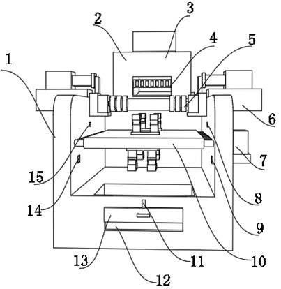
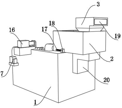
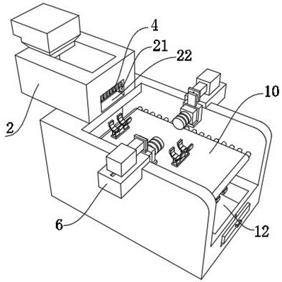
[0042] A deburring device for cast steel joints such as figure 1 , figure 2 , Figure 4 and Figure 5 As shown, including the body 1, the top outer wall of the body 1 is fixed with two fixing seats 6 by bolts, and the top outer walls of the two fixing seats 6 are provided with electric chute 23, and the inner walls of the two electric chute 23 pass through The slider is slidably connected with a hydraulic cylinder 16, and the extension ends of the two hydraulic cylinders 16 are fixed with a partition plate 26 by bolts, and the outer walls of one side of the two partition plates 26 are provided with a second electric slide rail 27. The inner walls of the two electric slide rails 27 are all slidably connected with connecting plates 30 by sliders, and the bottom outer walls of the two connecting plates 30 are fixed with a placing plate 29 by bolts. The placing plate 29 is an L-shaped structure, and the top of the two placing plates 29 The outer wall is fixed with a third moto...

Embodiment 2

[0053] A deburring method for the deburring device described in embodiment 1, such as Figure 9 shown, including the following steps:

[0054] S1: Feeding: put the joint into the feed box 3, enter the storage box 2 and wait for conveying and processing;

[0055]S2: Conveying and fixing: the joint falls onto the two electric expansion plates 35, and the cylinder 36 is adjusted so that the two clamping blocks 34 are driven by the electric expansion plate 35 to clamp the joint;

[0056] S3: grinding: start the third motor 28, and deburr the joint by adjusting the starting hydraulic cylinder 16 and the second electric slide rail 27;

[0057] S4: conveying and discharging: after the burrs are removed, start the cylinder 36 to make the treated joints break away from the clamping block 34;

[0058] S5: collect materials: collect materials in the discharge trough 12, just take it.


PUM


Abstract

The invention discloses a deburring device and a deburring method for cast steel joints, and relates to the technical field of joint deburring; in order to solve the problem that the inner hole of the joint is easily blocked; the equipment includes a body, and the top outer wall of the body is provided with Two fixed seats, the top outer walls of the two fixed seats are provided with electric chute, the inner walls of the two electric chute are provided with hydraulic cylinders, the extension ends of the two hydraulic cylinders are provided with partition plates, and the two partitions The outer wall of one side of the board is provided with a second electric slide rail, and the inner wall of the two second electric slide rails is provided with a connecting plate; the deburring method of the equipment includes the following steps: feeding; conveying and fixing; grinding; conveying and discharging; Collect materials. The invention adjusts the size of the inner hole of the distance grinding joint to ensure complete grinding, and removes burrs by grinding during rotation, so that the grinding wheel is in full contact with the inner cavity of the joint, avoiding the blockage of the inner hole and ensuring the deburring effect after grinding.

Description

technical field [0001] The invention relates to the technical field of joint deburring, in particular to a deburring device and a deburring method for cast steel joints. Background technique [0002] In the casting production process of steel castings, after the steel casting joints are processed, there will be thorns or flashes on the outer surface. These are called burrs. The burrs are very harmful and directly affect the quality of the workpiece. With industrialization and automation With the continuous improvement of the degree, the precision requirements for joint manufacturing are also constantly improving. Therefore, the treatment of burrs is a very important link in joint processing. Most of the deburring machines on the market now only deburr general workpieces. There are few devices that can deburr the joints. In the prior art, manual methods are often used to remove the burrs on the inner surface of the joints for irregularly shaped joints such as curved joints. T...

Claims


Application Information

Patent Timeline
Patent Type & Authority Patents(China)
IPC IPC(8): B24B9/04B24B41/00B24B41/06B24B1/00
CPCB24B1/00B24B9/04B24B41/00B24B41/06
Inventor 陈本香
Owner 济宁运河机械有限公司
Why Eureka
Try Eureka