
Full-automatic ultrasonic drilling two-in-one machine

An ultrasonic, two-in-one technology, applied in metal processing, etc., can solve the problems of reducing production efficiency, delaying production time, increasing production costs, etc., and achieves the effects of reducing bending or even breaking, reducing maintenance time, and reducing production costs

Active Publication Date: 2020-11-24
广州市振宇拉链机械有限公司
View PDF6 Cites 0 Cited by
  • Summary
  • Abstract
  • Description
  • Claims
  • Application Information

AI Technical Summary

Problems solved by technology

[0002] The production process of the zipper includes the steps of gluing, punching and inserting the upper and lower stops. When the upper and lower stops are made of plastic materials and the bottom stop is assembled, after one end of the zipper tape is glued and formed, it needs to be pressed on the zipper tape. The position after gluing is punched with a center hole and a positioning hole. The positioning hole is a small hole located around the center hole. The positioning hole is used for positioning when the bottom stop of injection molding is used. Ultrasonic technology is used to punch the center hole, and at the same time, the pin is used to punch the positioning hole, and the center hole and the positioning hole are processed at one time. Restrictions, the pin lacks a protective structure, which makes the pin prone to bending or even breaking, reducing the service life of the equipment. When repairing the equipment, it not only delays production time, reduces production efficiency, but also increases maintenance costs and production costs.

Method used


Image

  • Full-automatic ultrasonic drilling two-in-one machine
  • Full-automatic ultrasonic drilling two-in-one machine
  • Full-automatic ultrasonic drilling two-in-one machine

Examples


Embodiment Construction

[0033] In order to make the object, technical solution and advantages of the present invention more clear, the present invention will be further described in detail below in conjunction with the examples, but the protection scope of the present invention is not limited to the following specific examples.

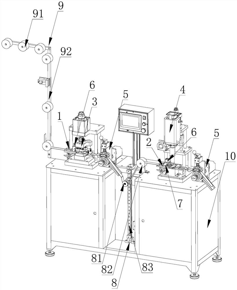
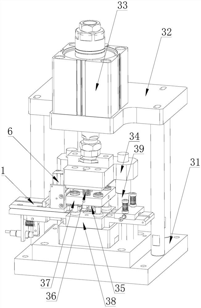
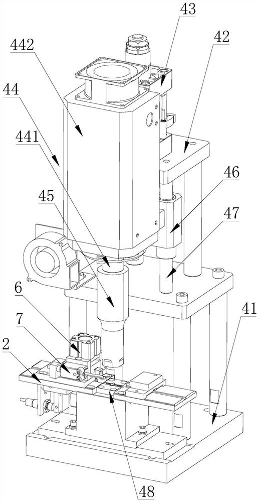
[0034] refer to Figure 1-11 , this embodiment discloses a fully automatic ultrasonic punching two-in-one machine, which is characterized in that it includes a base 10 on which a chain guide assembly 9, a first vacancy sensing assembly 1, and a positioning hole punching assembly are arranged. 3. The second vacancy sensing component 2, the center hole punching component 4 and the towing component 5;

[0035] The towing component 5 drives the zipper belt for conveying, and the zipper belt passes through the chain guide component 9, the first vacancy sensing component 1, the positioning hole punching component 3, the second vacancy sensing component 2 and the center hole punchi...


PUM


Abstract

The invention discloses a full-automatic ultrasonic drilling tow-in-one machine. The full-automatic ultrasonic drilling tow-in-one machine comprises a machine base, wherein a first vacancy positioninginduction assembly, a positioning hole drilling assembly, a second vacancy induction assembly, a central hole drilling assembly and a towing assembly are arranged on the machine base; and the positioning hole drilling assembly comprises a positioning hole mold, a plug pin and a first lifting driving device connected with the plug pin, the plug pin is located above the positioning hole mold, a buffer plate is arranged between the first lifting driving device and the positioning hole mold, the buffer plate is connected with the first lifting driving device through a spring, the plug pin is arranged in the buffer plate in a penetrating mode, the central hole drilling assembly comprises a central hole mold, an ultrasonic device and a second lifting driving device connected with the ultrasonicdevice, and the ultrasonic device is located above the central hole mold. The full-automatic ultrasonic drilling tow-in-one machine has the beneficial effects that the phenomenon of plug pin bendingor even breaking in the drilling process is avoided, the plug pin can be protected, the service life of the equipment is prolonged, the maintenance time is shortened, the maintenance cost is reduced,the production efficiency is improved, and the production cost is lowered.

Description

technical field [0001] The invention relates to the technical field of zipper processing, in particular to a fully automatic ultrasonic punching two-in-one machine. Background technique [0002] The production process of the zipper includes the steps of gluing, punching and inserting the upper and lower stops. When the upper and lower stops are made of plastic materials and the bottom stop is assembled, after one end of the zipper tape is glued and formed, it needs to be pressed on the zipper tape. The position after gluing is punched with a center hole and a positioning hole. The positioning hole is a small hole located around the center hole. The positioning hole is used for positioning when the bottom stop of injection molding is used. Ultrasonic technology is used to punch the center hole, and at the same time, the pin is used to punch the positioning hole, and the center hole and the positioning hole are processed at one time. Due to the lack of protective structure, t...

Claims


Application Information

Patent Timeline
Patent Type & Authority Applications(China)
IPC IPC(8): B26F1/24B26F1/26B26D7/06
CPCB26F1/24B26F1/26B26D7/06
Inventor 段军
Owner 广州市振宇拉链机械有限公司
Learn More