Gravity type soft bag unpacking machine
A bag opener and gravity type technology, applied in the field of gravity type soft bag opener, can solve the problems of scattering and dust, affecting the health of operators, waste and other problems, and achieve the effect of reducing labor intensity, reducing scattering and dust, and reducing waste.
- Summary
- Abstract
- Description
- Claims
- Application Information
AI Technical Summary
Problems solved by technology
Method used
Image
Examples
Embodiment 1
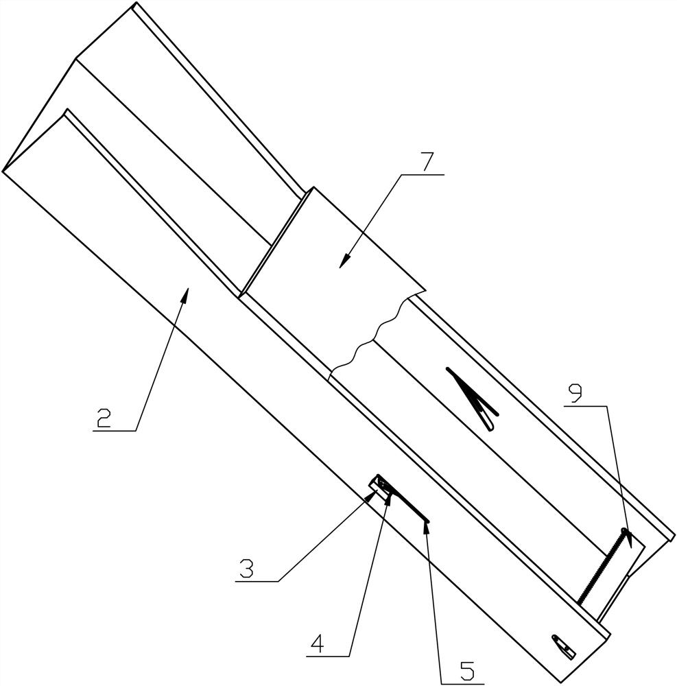
[0031] Such as figure 1 As shown, a gravity type soft bag unpacking machine includes a chute 2 with the right end inclined downward, two blades 4 respectively penetrating through the two side walls of the chute 2, and a blade 4 horizontally arranged at the lower right end of the chute 2. The cutter 9 at the feed opening, the angle between the chute 2 and the horizontal direction is 45 degrees.
[0032] The side walls of the chute 2 are provided with longitudinal first gaps 5 at the positions corresponding to the blades 4, and the two blades 4 are symmetrically arranged on the two side walls of the chute 2, and the two blades 4 are respectively arranged on the corresponding Inside the first gap 5. The blades of the two blades 4 are all inward, and the outer walls on both sides of the chute 2 are welded with a rectangular knife seat 3 below the blade 4, and the blade 4 is provided with a strip-shaped through hole consistent with the direction of the blade 4. Screws for fixedly...
Embodiment 2
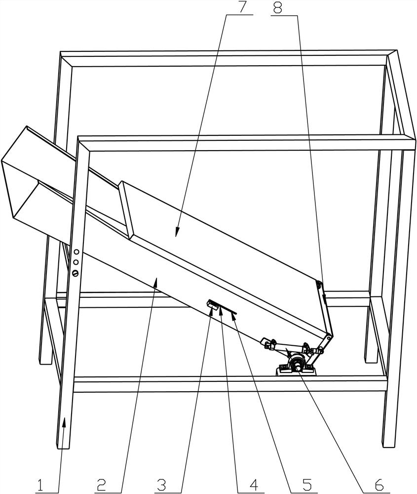
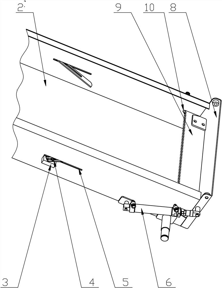
[0042] Such as figure 2 and image 3 As shown, a gravity type soft bag unpacking machine includes a chute 2 with the right end inclined downward, two blades 4 respectively penetrating through the two side walls of the chute 2, and a blade 4 horizontally arranged at the lower right end of the chute 2. Cutter 9 at the material opening.
[0043]The side walls of the chute 2 are provided with longitudinal first gaps 5 at the positions corresponding to the blades 4, and the two blades 4 are symmetrically arranged on the two side walls of the chute 2, and the two blades 4 are respectively arranged on the corresponding Inside the first gap 5. The blades of the two blades 4 are all inward, and the outer walls on both sides of the chute 2 are welded with a rectangular knife seat 3 below the blade 4, and the blade 4 is provided with a strip-shaped through hole consistent with the direction of the blade 4. Screws for fixedly connecting the blade 4 with the corresponding knife seat 3 ...
Embodiment 3
[0056] Such as Figure 5 and Figure 6 As shown, the difference between this embodiment and embodiment 2 is:
[0057] 1. A window is opened in the middle part of the cover plate 7 near the blade 4, and a negative pressure bag taking device 13 fixedly connected to the frame 1 is arranged above the window;
[0058] 2. Two transverse through holes are opened at the bottom of the chute 2 close to the blade 4, and a closed negative pressure box 11 is welded at the bottom of the chute 2 at the position of the through hole, and the negative pressure box 11 passes through the pipeline Connected to the suction device.
[0059] The negative pressure bag taking device 13 includes a vertical guide tube 1301, the bottom of the guide tube 1301 is a bell mouth facing the window, the center of the guide tube 1301 is provided with a vertical suction pipe 1303, and the suction pipe 1303 is connected to the guide tube. There are gaps between the tubes 1301 . The middle part of the guide pipe...
PUM
 Abstract
Description
Claims
Application Information
 - R&D
- Intellectual Property
- Life Sciences
- Materials
- Tech Scout
- Unparalleled Data Quality
- Higher Quality Content
- 60% Fewer Hallucinations
Browse by: Latest US Patents, China's latest patents, Technical Efficacy Thesaurus, Application Domain, Technology Topic, Popular Technical Reports.
© 2025 PatSnap. All rights reserved.Legal|Privacy policy|Modern Slavery Act Transparency Statement|Sitemap|About US| Contact US: help@patsnap.com


