Continuous annealing line gear coupling fault detection device, system and method

A gear coupling and fault detection technology, which is applied in the direction of measuring devices, machine/structural component testing, instruments, etc., can solve the problems of maintenance delay and fault detection lag, so as to improve safety, reduce downtime, The effect of reducing labor intensity

Active Publication Date: 2020-11-24
MAANSHAN IRON & STEEL CO LTD
View PDF26 Cites 3 Cited by
  • Summary
  • Abstract
  • Description
  • Claims
  • Application Information

AI Technical Summary

Problems solved by technology

[0007] Aiming at the problems of relative lag in fault detection and maintenance delay in the prior art of continuous retreat gear couplings, the present invention provides a fault detection device for continuous retreat gear couplings, which can detect the gear couplings at the first time. Coupling failure improves troubleshooting and maintenance efficiency, thereby avoiding strip quality problems caused by delay in troubleshooting;

Method used


Image

  • Continuous annealing line gear coupling fault detection device, system and method
  • Continuous annealing line gear coupling fault detection device, system and method
  • Continuous annealing line gear coupling fault detection device, system and method

Examples


Embodiment 1

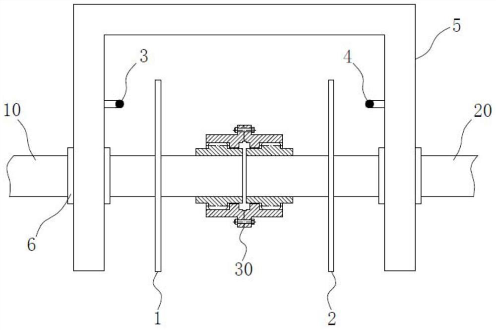
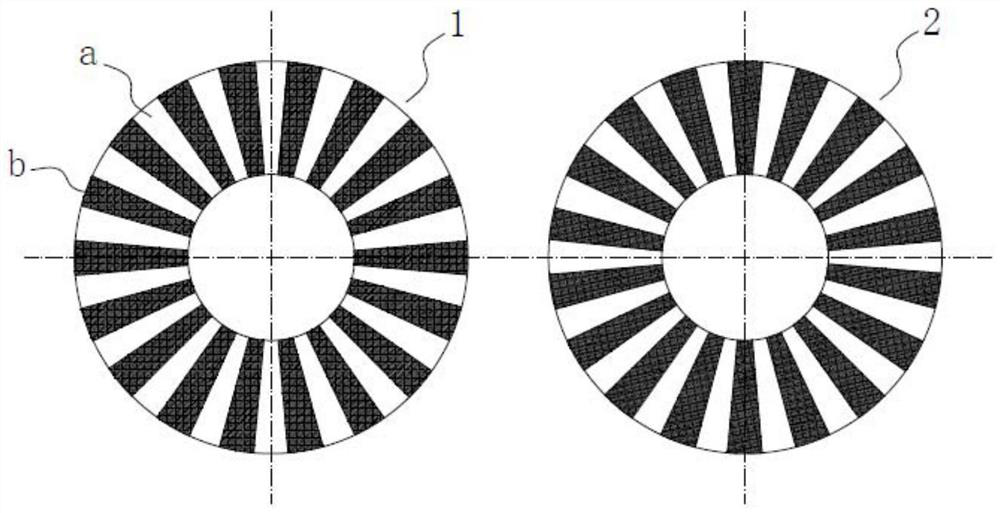
[0035] like figure 1 and figure 2 As shown in , a device for fault detection of a gear coupling with continuous retraction line in this embodiment includes a first ring grating 1 and a second ring grating 2, the two ring gratings have the same structure, and both have fan-shaped light-shielding areas a and the light-transmitting area b, the light-shielding area a and the light-transmitting area b are uniformly and alternately distributed around the axis of the ring grating; a photoelectric sensor is also included, and the photoelectric sensor has a light source emitting end 3 and a receiving end 4; the two The ring gratings are coaxially fitted and fixedly connected with the driving shaft 10 and the driven shaft 20 connected to the two ends of the gear coupling 30 respectively, and the light-shielding area a on the first ring grating 1 and the transparent area a on the second ring grating 2 The light zone b overlaps in the axial direction, the light source emitting end 3 and...

Embodiment 2

[0040] This embodiment provides a detection system including the fault detection device for the gear coupling with continuous withdrawal line described in Embodiment 1. The detection system is used for real-time detection and monitoring of whether the gear couplings in the continuous withdrawal line have wear, sliding teeth and broken teeth.

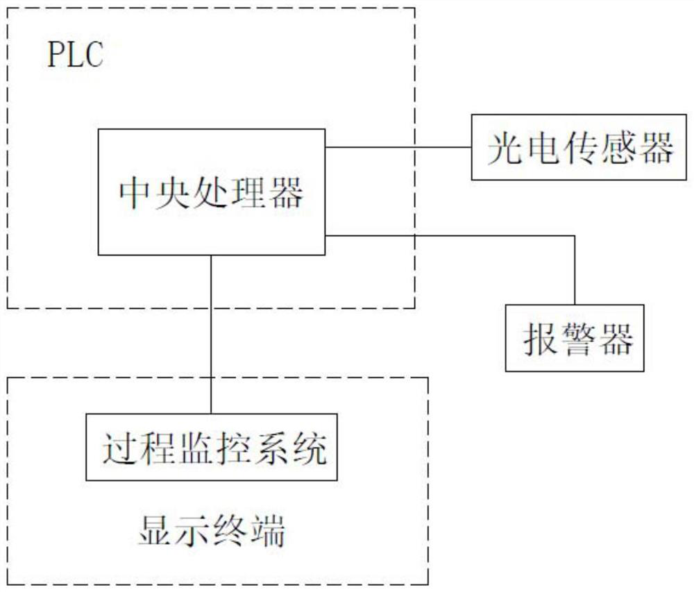
[0041] like image 3 As shown in , the detection system in this embodiment includes several detection devices and PLC control systems that correspond one-to-one to the gear couplings 30 in the continuous withdrawal line, and the photoelectric sensors in the detection devices are connected to all The PLC control system is used to receive and analyze the signal fed back by the receiving end 4 of the photoelectric sensor through the PLC control system, and output prompt information to the staff.

[0042] like image 3 As shown in , the detection system in this embodiment also includes several alarms connected to the PLC control system, an...

Embodiment 3

[0046] This embodiment provides a detection method based on the detection system described in Embodiment 2, the steps are:

[0047] 1. While starting the continuous retreat line, the light source transmitting end 3 of the photoelectric sensor at the position of each gear coupling 30 is controlled by the PLC control system to continuously emit light signals to its receiving end 4;

[0048] 2. The PLC control system scans the feedback signal of the photoelectric sensor at the position of each gear coupling 30 with a signal scanning period of 100 ms. When the gear coupling 30 at a certain position has wear, slipping and broken teeth , the receiving end 4 of the photoelectric sensor at this position converts the received optical signal into an electrical signal and feeds it back to the central processing unit of the PLC control system;

[0049] 3. After receiving the signal, the central processor of the PLC control system sends an instruction to the alarm at the corresponding posi...


PUM


Abstract

The invention discloses a continuous annealing line gear coupling fault detection device, system and method, and relates to the field of continuous annealing production lines. The device comprises twoannular gratings with the same structure, and each annular grating is provided with a shading area and a light-transmitting area which are uniformly and alternately distributed around the axis of theannular grating; the device further comprises a photoelectric sensor which is provided with a light source transmitting end and a light source receiving end; the two annular gratings are coaxially matched and fixedly connected with a driving shaft and a driven shaft which are connected with the two ends of a gear coupling respectively, the shading area on one annular grating coincides with the light-transmitting area on the other annular grating in the axial direction, and the light source transmitting end and the light source receiving end are oppositely fixed to the outer sides of the two annular gratings. The system comprises a plurality of detection devices in one-to-one correspondence with gear couplings in a continuous annealing line, and a PLC control system, the method performs real-time remote monitoring on the continuous annealing line based on the system. According to the invention, the fault of the continuous annealing line gear coupling can be detected in time, the product quality is ensured, and the safety is high.

Description

technical field [0001] The invention relates to the field of continuous annealing production lines, in particular to a gear coupling fault detection device, system and method for continuous annealing lines. Background technique [0002] There are a large number of main drive motors and furnace roller motors in the silicon steel continuous annealing line. These motors and their driven shafts (rolls) are usually connected by gear couplings. Since the gear couplings bear a large load, Serious tooth wear will occur during use, and even lead to slipping or broken teeth. Among them, once the above-mentioned failure occurs in the gear coupling at the main drive motor, the tension of the strip steel will fluctuate; and if the above-mentioned failure occurs in the gear coupling at the furnace roller motor, the speed of the furnace roller will be reduced, and even the furnace roller will be damaged. Become a free roll, resulting in a speed difference between the furnace roll and the ...

Claims


Application Information

Patent Timeline
Patent Type & Authority Applications(China)
IPC IPC(8): G01M13/022G01M13/021
CPCG01M13/022G01M13/021
Inventor 胡德勇严开龙汪红兵杜克飞林攀付军发徐朝军常文亮罗健红
Owner MAANSHAN IRON & STEEL CO LTD
Why Eureka
Try Eureka