Special quality detection equipment for building bricks

A technology for testing equipment and bricks, applied in the direction of applying stable tension/pressure to test the strength of materials, measuring devices, conveyor objects, etc., to achieve the effect of accurate detection results

Pending Publication Date: 2020-11-24
邢海龙
View PDF1 Cites 6 Cited by
  • Summary
  • Abstract
  • Description
  • Claims
  • Application Information

AI Technical Summary

Problems solved by technology

[0005] In order to overcome the shortcomings in the existing brick detection technology that it is necessary to manually move the bricks, manually open the detection equipment to detect the bricks and manually take out the detected bricks, the technical problem to be solved is: to provide a method that can automatically remove the bricks. The bricks are accurately pushed to the bottom of the detection mechanism, the bricks are loaded and tested, and the bricks that have been tested are automatically taken out. The special quality inspection equipment for construction bricks

Method used


Image

  • Special quality detection equipment for building bricks
  • Special quality detection equipment for building bricks
  • Special quality detection equipment for building bricks

Examples


Embodiment 1

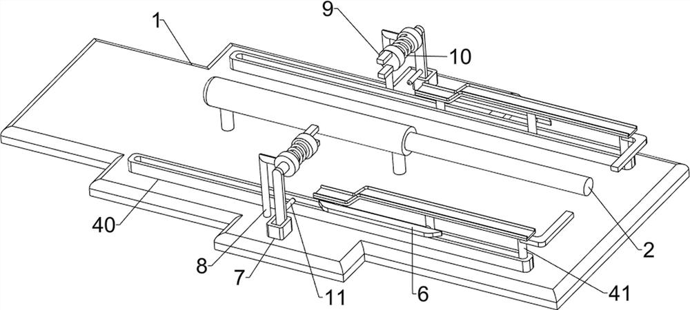
[0025] A special quality inspection equipment for building bricks, such as figure 1 As shown, it includes a base 1, an electric push rod 2, a pusher mechanism 3, a detection mechanism 4 and a blanking frame 5, an electric push rod 2 is arranged in the middle of the top of the base 1, and a pusher mechanism 3 is arranged on the front and rear sides of the top of the base 1 , the pusher mechanism 3 is connected with the electric push rod 2, the detection mechanism 4 is provided on the middle side of the top of the base 1, the detection mechanism 4 is connected with the pusher mechanism 3, the top left side of the base 1 is evenly equipped with a blanking frame 5, and the blanking frame 5 The number is 3, and the right end of the blanking rack 5 is all connected with the pushing mechanism 3.

[0026] When people need to inspect the quality of building bricks, they place the bricks on the parts of the pusher mechanism 3, and they start the electric push rod 2, and the telescopic r...

Embodiment 2

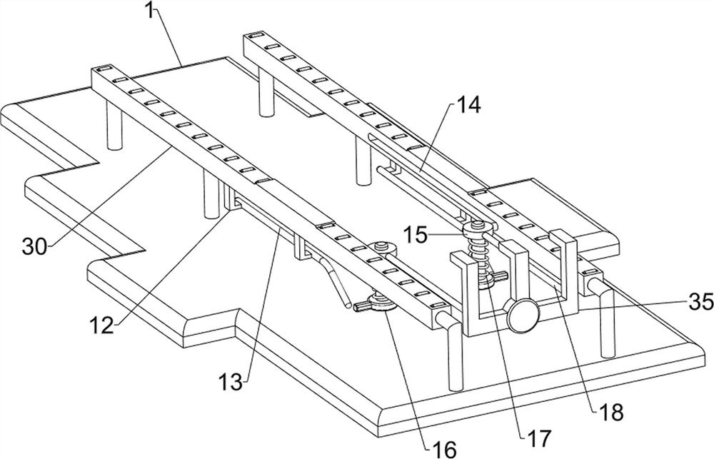
[0028] On the basis of Example 1, such as Figure 2-4 As shown, the pushing mechanism 3 includes a placement frame 30, a roller 31, a mounting block 32, a guide frame 33, a compression spring 34 and a push frame 35, and a placement frame 30 is connected between the front and rear sides of the base 1 top, and the placement frame 30 The top is evenly provided with rollers 31, and the left and right sides of the placement frame 30 are symmetrically provided with mounting blocks 32, and a guide frame 33 is slidably connected between the mounting blocks 32 on the front side and the rear side. Compression springs 34 are connected between them, and the compression springs 34 are all sleeved on the guide frame 33. A push frame 35 is connected between the right ends of the placement frame 30. The push frame 35 is connected with the parts of the detection mechanism 4, and the push frame 35 is connected with the electric push rod 2. The telescopic rod is connected.

[0029] When people ...

Embodiment 3

[0033] On the basis of Example 2, such as Figure 5-7 As shown, it also includes a wedge plate 6, a guide rail 7, a third sliding sleeve 8, a locking rod 9, a first spring 10 and a contact rod 11. The lower side of the sliding frame 41 is symmetrically provided with a wedge plate 6, and the top of the base 1 The middle side is symmetrically provided with a guide rail 7, and the guide rail 7 is located on the left side of the first sliding sleeve 43, and the middle side of the top of the base 1 is symmetrically provided with a third sliding sleeve 8, and the third sliding sleeve 8 is located on the left side of the guide rail 7 , the right part of the third sliding sleeve 8 is symmetrically slidably connected with a clamping rod 9, the clamping rod 9 is slidingly connected with the guide rail 7, and the first spring 10 is connected between the clamping rod 9 and the third sliding sleeve 8 , the first springs 10 are both sleeved on the clamping rod 9, and the lower side of the c...


PUM


Abstract

The invention relates to quality detection equipment, and in particular, relates to special quality detection equipment for building bricks. Provided is the special quality detection equipment for thebuilding bricks, the bricks can be automatically and accurately pushed to the position below a detection mechanism, bearing detection is carried out on the bricks, and the detected bricks are automatically taken out. The special quality detection equipment for the building bricks comprises a base, an electric push rod, pushing mechanisms, a detection mechanism and blanking frames; the electric push rod is arranged in the middle of the top of the base. The pushing mechanisms are arranged on the two sides of the top of the base, and are connected with a telescopic rod of the electric push rod;the detection mechanism is arranged on the middle side of the top of the base, and the detection mechanism is connected with the pushing mechanisms; the blanking frames are evenly arranged on the leftside of the top of the base and connected with the pushing mechanisms. According to the special quality detection equipment for the building bricks, the effects that bricks needing to be detected canbe accurately pushed to the position below the transmission frame, the bearing capacity of the bricks is detected, and the detected bricks are pushed to the blanking frames automatically can be achieved.

Description

technical field [0001] The invention relates to a quality testing device, in particular to a special quality testing device for building bricks. Background technique [0002] With the continuous innovation of society, my country's construction industry is developing rapidly. Bricks are one of the most common materials in the construction industry. Bricks need to be tested for their load-bearing strength before they are used. Generally, manual brick quality testing requires people to move them manually. Bricks go to the detection equipment, and then start the detection equipment to detect the bricks. After the brick detection is completed, people need to manually take out the detected bricks. The operation is complicated and the work efficiency of brick detection is low. [0003] Patent application CN205656087U discloses a safety type brick quality detection device for construction sites. Its structure mainly includes a bottom plate, a box body, an electric winding wheel, an e...

Claims


Application Information

Patent Timeline
IPC IPC(8): G01N3/02G01N3/04G01N3/08B65G47/82
CPCB65G47/82G01N3/02G01N3/04G01N3/08
Inventor 邢海龙
Owner 邢海龙
Why Eureka
Try Eureka