Frequency response test method

A technology of frequency response testing and frequency response, applied in the electronic field, can solve problems such as low signal-to-noise ratio of the measured signal, uncertain bandwidth of the measured signal, difficulty in filter design, etc., and achieve stable triggering and convenient measurement of parameters

Pending Publication Date: 2020-11-24
SUZHOU RIGOL PRECISION ELECTRIC TECH
View PDF5 Cites 0 Cited by
  • Summary
  • Abstract
  • Description
  • Claims
  • Application Information

AI Technical Summary

Problems solved by technology

However, since the signal-to-noise ratio of the measured signal is often very low, and the

Method used


Image

  • Frequency response test method
  • Frequency response test method
  • Frequency response test method

Examples


Embodiment Construction

[0021] The following will clearly and completely describe the technical solutions in the embodiments of the application with reference to the drawings in the embodiments of the application. Apparently, the described embodiments are only some of the embodiments of the application, not all of them. Based on the embodiments in this application, all other embodiments obtained by persons of ordinary skill in the art without making creative efforts belong to the scope of protection of this application.

[0022] At present, due to the low signal-to-noise ratio of the measured signal, an oscilloscope is required to be able to trigger stably when measuring parameters. Therefore, when using an oscilloscope in the existing scheme, it is necessary to add a step of filtering the collected signal. Due to the cost of using hardware filtering High, and the measured signal bandwidth is uncertain, so the solution has high requirements on filter cost and performance.

[0023] In view of the abov...


PUM


Abstract

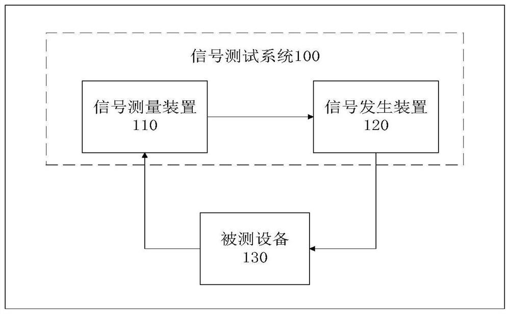
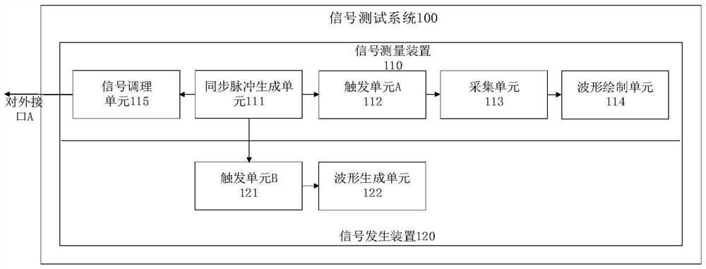
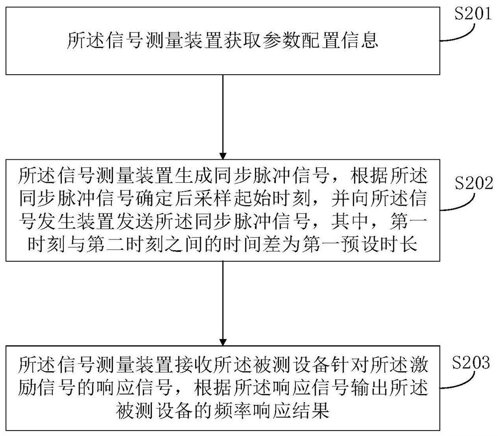
The embodiment of the invention provides a frequency response test method. The signal testing method is applied to a signal measuring device of a signal testing system, the signal testing system comprises the signal measuring device and a signal generating device, the signal measuring device is connected with the signal generating device, the signal generating device is connected with tested equipment, and the tested equipment is connected with the signal measuring device. The method comprises the steps: the signal measuring device acquires parameter configuration information, and the signal measuring device generates a synchronous pulse signal; a post-sampling starting moment is determined according to the synchronous pulse signal, the synchronous pulse signal is sent to the signal generating device, a response signal of the tested equipment for the excitation signal is received by the signal measuring device, and a frequency response result of the tested equipment is outputted according to the response signal. Therefore, stable triggering of the low signal-to-noise ratio signal on the signal measuring device can be realized without designing a complex filter, and parameter measurement is facilitated.

Description

technical field [0001] This application relates to the field of electronics, in particular to a frequency response testing method. Background technique [0002] The main function of the oscilloscope is to display the waveform of the electrical signal. The change of the electrical signal can be observed on the fluorescent screen. At the same time, the electrical signal can be qualitatively and quantitatively analyzed and measured. Usually, the oscilloscope can be used to measure the amplitude, phase, frequency, etc. of the electrical signal. parameter. Oscilloscopes are widely used in communication product design, education and teaching, laboratories, digital circuit design and other fields. Today's oscilloscopes are very rich in functions. However, since the signal-to-noise ratio of the measured signal is often very low, and the bandwidth of the measured signal is uncertain, the design of the filter is very difficult. Contents of the invention [0003] The embodiment of ...

Claims


Application Information

Patent Timeline
IPC IPC(8): G01R23/02G01R23/16
CPCG01R23/02G01R23/16
Inventor 严波郝虎虎索世昌冯红开王悦
Owner SUZHOU RIGOL PRECISION ELECTRIC TECH
Why Eureka
Try Eureka