Al technical title is built by PatSnap Al team. It summarizes the technical point description of the patent document.
A temperature control and portable technology, applied in the direction of temperature control, non-electric variable control, control/regulation system, etc., can solve the problems of reduced PLC work efficiency, inconvenient handling, reduced work efficiency, etc., to avoid work efficiency reduction, operation The site is flexible and changeable, and the effect of accelerating heat dissipation
Inactive Publication Date: 2020-11-24
吴江市太浦电器有限公司
View PDF4 Cites 1 Cited by
Summary
Abstract
Description
Claims
Application Information
AI Technical Summary
This helps you quickly interpret patents by identifying the three key elements:
Problems solved by technology
Method used
Benefits of technology
Problems solved by technology
[0003] In the process of material solidification and forming, temperature has a direct impact on the quality of material forming, so the temperature control of the material is very important, so a portable temperature control terminal is needed to achieve temperature control, but the general temperature control terminal volume It is large, inconvenient to carry, and has high requirements on the site during use, which is inconvenient to use. At the same time, there is a PLC inside the temperature control terminal, which will generate more heat during work. If the heat is not dissipated in time, the working efficiency of the PLC will be reduced, which is serious. It will even shorten the service life of the equipment, and the forming of multiple pieces of material is often involved in the process of material forming, but the common setting can provide fewer interfaces, which is not very practical, and at the same time, it takes time to splice and install during use laborious, reducing work efficiency
Method used
Image
Click on the blue label to locate the original text in one second.
Reading with bidirectional positioning of images and text.
Examples
Embodiment Construction
[0023] The following will clearly and completely describe the technical solutions in the embodiments of the present invention with reference to the accompanying drawings in the embodiments of the present invention. Obviously, the described embodiments are only some, not all, embodiments of the present invention. Based on the embodiments of the present invention, all other embodiments obtained by persons of ordinary skill in the art without making creative efforts belong to the protection scope of the present invention.
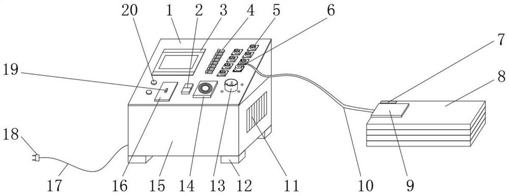
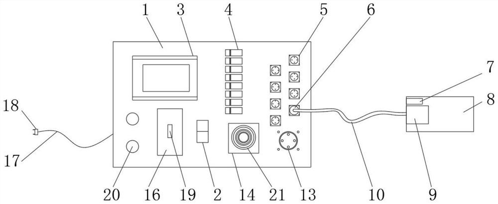
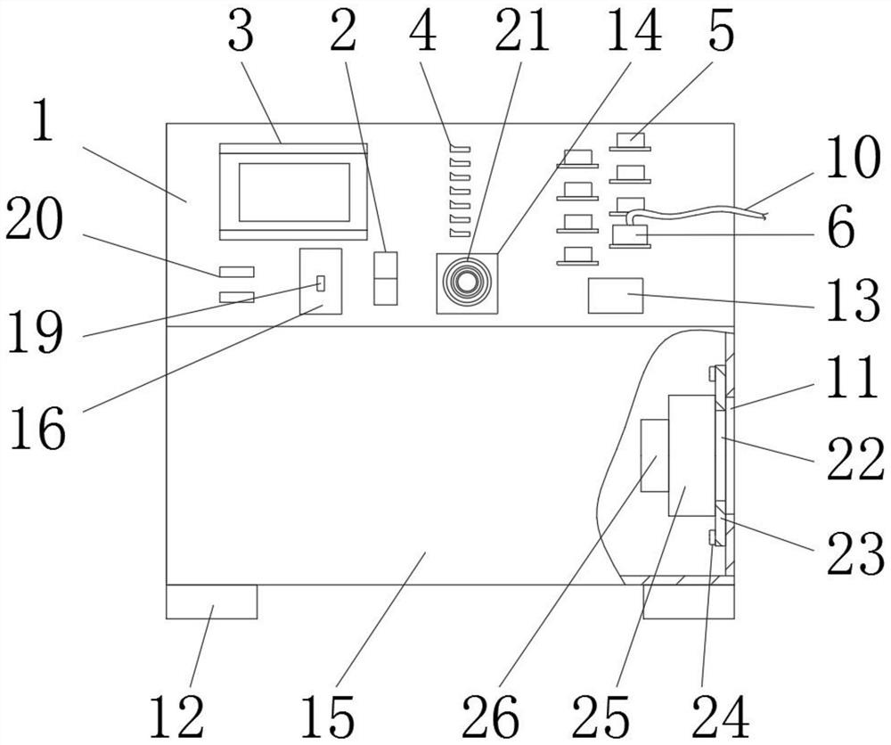
[0024] see Figure 1-5 , a portable temperature control terminal, including a control panel 1, a first air switch 2, a display screen 3, a second air switch 4, a first aviation socket 5, an aviation plug 6, a temperature sensor 7, a heating plate 8, Protective plate 9, cable 10, first through hole 11, base 12, second aviation socket 13, first fixed plate 14, box body 15, second fixed plate 16, power cord 17, power plug 18, fixed block 19 , overcurrent protect...
PUM
Abstract
The invention discloses a temperature control terminal based on portability. The temperature control terminal comprises a control panel, a first air switch, a display screen, a second air switch, a first aviation socket, an aviation plug, a temperature sensor, a hot pressing plate, a protection plate, a cable, a first through hole, a base, a second aviation socket, a first fixing plate, a box body, a second fixing plate, a power line, a power plug, a fixing block, an overcurrent protection switch, a groove, a second through hole, a mounting plate, bolts, a draught fan, air ducts, insulating layers and film resistors. The temperature control terminal has the advantages of portability, flexibility and the like; volume and mass are reduced, the temperature control terminal is simple in structure and easy to operate, a graphical interface is adopted, related information is directly read on the display screen, heat generated when the temperature control terminal works is blown out from thefirst through hole through the draught fan, dissipation of the device heat is accelerated, the expansion capacity is high, working channels are expanded by additionally arranging a PLC hardware moduleaccording to technological requirements, and the number of equipment channels can be increased.
Description
technical field [0001] The invention relates to the technical field of material processing equipment, in particular to a portable temperature control terminal. Background technique [0002] Material forming refers to the process of forming a material into a stable shape by using a process or equipment. [0003] In the process of material solidification and forming, temperature has a direct impact on the quality of material forming, so the temperature control of the material is very important, so a portable temperature control terminal is needed to achieve temperature control, but the general temperature control terminal volume It is large, inconvenient to carry, and has high requirements on the site during use, which is inconvenient to use. At the same time, there is a PLC inside the temperature control terminal, which will generate more heat during work. If the heat is not dissipated in time, the working efficiency of the PLC will be reduced, which is serious. It will even...
Claims
Application Information
Patent Timeline
Application Date:The date an application was filed.
Publication Date:The date a patent or application was officially published.
First Publication Date:The earliest publication date of a patent with the same application number.
Issue Date:Publication date of the patent grant document.
PCT Entry Date:The Entry date of PCT National Phase.
Estimated Expiry Date:The statutory expiry date of a patent right according to the Patent Law, and it is the longest term of protection that the patent right can achieve without the termination of the patent right due to other reasons(Term extension factor has been taken into account ).
Invalid Date:Actual expiry date is based on effective date or publication date of legal transaction data of invalid patent.