A Design Method of Straight Barrel Combination for Miniaturized Optical Microscope

An optical microscope and combined design technology, applied in the optical field, can solve the problems of microscope application limitations, large microscope volume, inconvenient operation, etc., and achieve the effects of flexible size design, high light efficiency utilization, and convenient portability

Active Publication Date: 2022-05-03
HUBEI UNIV
View PDF5 Cites 0 Cited by
  • Summary
  • Abstract
  • Description
  • Claims
  • Application Information

AI Technical Summary

Problems solved by technology

[0003] Due to the large volume of traditional microscopes, most of them are placed on the instrument table in the laboratory, and there are certain requirements for the use environment, which limits the application of the microscope
With the development of technology, the imaging quality of microscopes is constantly improving, but many new high-resolution microscopes are more bulky. When people work in the field, they will have problems such as inconvenient to carry, inconvenient to place, and inconvenient to operate.

Method used


Image

  • A Design Method of Straight Barrel Combination for Miniaturized Optical Microscope
  • A Design Method of Straight Barrel Combination for Miniaturized Optical Microscope
  • A Design Method of Straight Barrel Combination for Miniaturized Optical Microscope

Examples


Embodiment 1

[0041] A design method for a straight barrel combination of a miniaturized optical microscope, comprising the following steps:

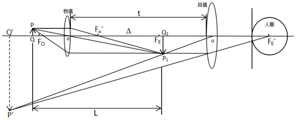
[0042] Step 1. Determine the optical path structure of the microscope. The optical path structure of the microscope includes an eyepiece and an objective lens;

[0043] Step 2. Calculate the objective focal length f of the objective lens o And the optical tube length Δ;

[0044] Step 3. Determine the minimum system magnification according to the resolution angle of the human eye and the numerical aperture of the objective lens;

[0045] Step 4. Determine the reduction ratio according to the minimum system magnification and the basic system magnification. The system basic magnification is the product of the objective lens magnification and the eyepiece magnification, and the reduction ratio is the minimum system magnification divided by the basic system magnification;

[0046] Step 5. Reduce the optical tube length Δ according to the reduction rati...

Embodiment 2

[0058] Taking a standard microscope system composed of a 10x objective lens and a 12.5x eyepiece as an example, a design method of straight tube combination for a miniaturized optical microscope is illustrated. The method proposed by the present invention includes but is not limited to this combination of parameters.

[0059] A design method for a straight barrel combination of a miniaturized optical microscope, comprising the following steps:

[0060] Step 1. Determine the optical path structure of the microscope. The optical path structure of the microscope includes an eyepiece and an objective lens, and an aberration correction lens group is arranged between the eyepiece and the objective lens;

[0061] according to figure 1 As shown in the optical path diagram, it can be seen that the optical path structure of the microscope is mainly an optical system composed of an eyepiece and an objective lens. The length of the mechanical tube is t, and the conjugate distance is L. ...


PUM


Abstract

The invention discloses a design method for a miniaturized optical microscope with a straight barrel combination, which determines the optical path structure of the microscope, calculates the object focal length of the objective lens and the length of the optical barrel, determines the minimum system magnification, determines the reduction ratio, and reduces the optical barrel according to the reduction ratio Long, calculate the conjugate distance after reduction, add aberration correction lens group, simulate and adjust in the optical simulation software, so that the object imaging can be clearly distinguished, and connect the objective lens and eyepiece with the lens barrel of different lengths in a straight cylinder type, design Auxiliary illumination system for miniaturized microscope systems. The microscope of the invention is small in size, easy to carry, has excellent imaging quality, and can obtain miniaturized systems with different magnifications. In addition, a matching auxiliary lighting system is also designed, which can introduce an external light source to provide illumination for the observed sample, and at the same time play a supporting role, which can help adjust and fix the position of the microscope to obtain a clear image.

Description

technical field [0001] The invention belongs to the field of optical technology, and in particular relates to a design method of a straight cylinder combination of a miniaturized optical microscope. Background technique [0002] Before the 20th century, human beings only observed objects in the world with the naked eye or a hand-held magnifying glass, and could not see tiny substances. It was not until human beings invented the microscope, an optical instrument, that they began to have a new understanding of the microscopic world. A microscope is an optical instrument composed of a combination of one or several lenses. It opens a new door to human vision and allows humans to see a whole new world. From the first time people saw tiny substances, to today's microscopes have played a huge role in medical equipment, biological research, and material science. An indispensable instrument that is needed. [0003] Due to the large volume of traditional microscopes, most of them ar...

Claims


Application Information

Patent Timeline
Patent Type & Authority Patents(China)
IPC IPC(8): G02B27/00G02B21/06G02B21/08
CPCG02B27/0012G02B21/06G02B21/08G02B27/0025
Inventor 熊晖吴淑贞
Owner HUBEI UNIV
Why Eureka
Try Eureka