Controlled agricultural system and method for agriculture

An agricultural, growing area technology, applied in the field of controlled agricultural systems, that can solve the problems of traditional agricultural constraints, poor soil, etc.

Pending Publication Date: 2020-11-24
FLUENCE BIOENG INC
View PDF20 Cites 15 Cited by
  • Summary
  • Abstract
  • Description
  • Claims
  • Application Information

AI Technical Summary

Problems solved by technology

[0007] Despite the ever-decreasing energy consumption of artificial lighting, driven especially by LED technology, conventional agriculture faces increasing constraints
Not only are there drawbacks of monocrop farming, over fertilization and poor soil, but huge harvesters on huge fields use fuel too much

Method used


Image

  • Controlled agricultural system and method for agriculture
  • Controlled agricultural system and method for agriculture
  • Controlled agricultural system and method for agriculture

Examples


Embodiment Construction

[2303] The detailed description is described with reference to the accompanying drawings. In the context of this specification, the terms "connected" and "coupled" are used to describe both direct and indirect connections as well as direct or indirect couplings.

[2304] system settings

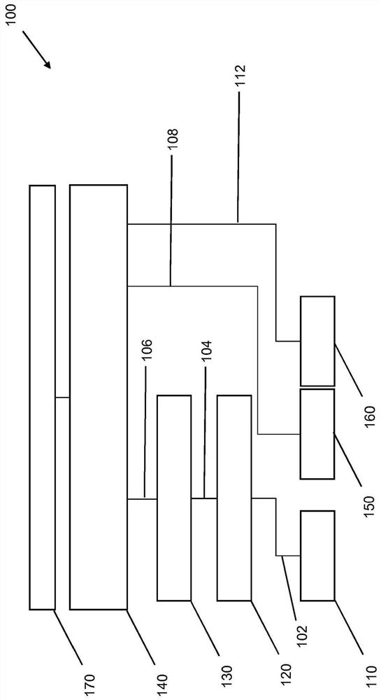
[2305] figure 1 A controlled farming system 100 according to various embodiments is schematically shown.

[2306] The agricultural light fixture 110 is connected to a smart driver unit 120 . The smart driver unit 120 is configured to send the first signal 102 to the agricultural light fixture 110 . The connection between the agricultural lamp 110 and the smart driver unit 120 may be wired or wireless. Transmit signal 102 may conform to a common communication protocol. The smart driver unit 120 is connected to the light control unit 130 . The light control unit 130 is configured to send the second signal 104 to the smart driver unit 120 . The first signal 102 is based on the second si...


PUM


Abstract

The present disclosure relates to the control of an agricultural system, for example, control of a growth area (350) having a plurality of growth locations (404) for growing a plants, wherein a distance between the growth locations (404) is adjustable. Furthermore, the disclosure relates to a method for agriculture.

Description

technical field [0001] The present disclosure relates to a controlled agricultural system, an agricultural lamp for use in the controlled agricultural system, and a method of agricultural management. Background technique [0002] Agriculture has been a success story for millennia. From the first plowshares to today's state-of-the-art harvesters, from the early use of minerals and fertilizers by the Egyptians, Romans and Babylonians to today's tailor-made fertilizers, from early plant breeding to genetic engineering, farming cultures allow for harvest Steady increase. Despite these dramatic changes, one of the fundamentals has remained the same, and from then until today, plant growth has been driven by natural sunlight. This success story began at the end of the Ice Age, about [0003] Bring the plant to the light. [0004] The story of this application is about [0005] Bring the light to the plants. [0006] Not just the lighting, but the entire environment of the fa...

Claims


Application Information

Patent Timeline
Patent Type & Authority Applications(China)
IPC IPC(8): A01G7/04A01G31/02A01G9/029
CPCA01G9/0297A01G31/02Y02P60/21G06Q50/02A01G9/247A01G31/042G06Q10/0639
Inventor 蒂莫·邦加茨塞巴斯蒂安·奥尔朔维斯基诺贝特·哈斯吉多·安格嫩特马雷克·布尔扎诺贝特·马格
Owner FLUENCE BIOENG INC
Why Eureka
Try Eureka