
Ultrasonic atomization core and ultrasonic atomizer

An ultrasonic and atomizing core technology, applied in tobacco and other directions, can solve the problems of unsatisfactory oil guiding effect, affecting the taste of smoke, and prone to dry burning, etc., to prevent insufficient ultrasonic atomization, good oil guiding effect, and prevent dry burning effect

Active Publication Date: 2020-11-27
CHINA TOBACCO HUNAN INDAL CORP
View PDF12 Cites 0 Cited by
  • Summary
  • Abstract
  • Description
  • Claims
  • Application Information

AI Technical Summary

Problems solved by technology

[0002] Chinese patent 2016208984658 discloses an ultrasonic electronic atomizer. The ultrasonic atomizing sheet is vertically placed in the electronic cigarette casing, the oil guide cotton is placed in the same direction as the ultrasonic atomizing sheet, and the oil tank is set at the bottom. The e-liquid needs to be transmitted to the atomization surface of the ultrasonic atomizer through the oil guide rod, oil storage cotton, and oil guide cotton. Cotton conveying process, so the oil guide effect is not very ideal, prone to dry burning
[0003] Additionally, if figure 1 As shown, the airflow inlet A and the airflow outlet B of the atomizing core with the existing ultrasonic atomizing sheet placed vertically are set parallel to the ultrasonic atomizing sheet C, so that the airflow passes through the surface of the oil-conducting cotton E, so it is easy to displace the oil-conducting cotton The smoke oil particles on the surface are taken out of the atomization chamber D together, and finally inhaled by the user, affecting the taste of the smoke

Method used


Image

  • Ultrasonic atomization core and ultrasonic atomizer
  • Ultrasonic atomization core and ultrasonic atomizer
  • Ultrasonic atomization core and ultrasonic atomizer

Examples


Embodiment 1

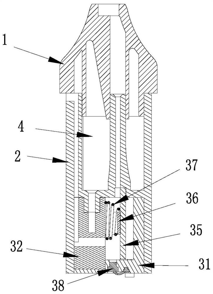
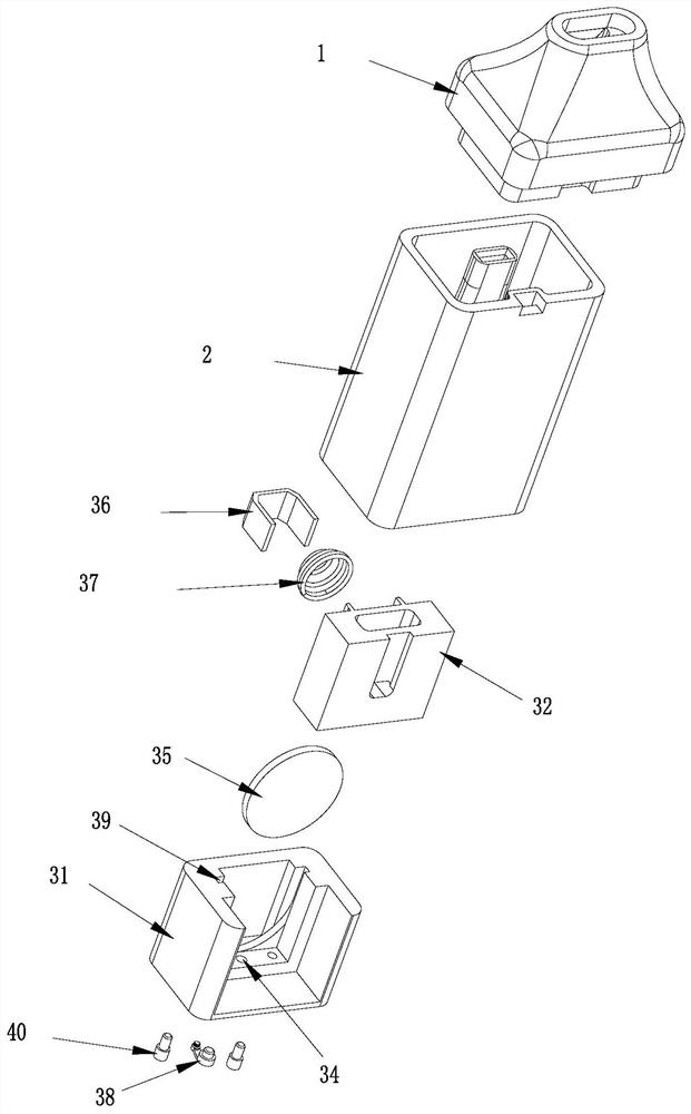
[0036] Such as figure 2 - Figure 10 As shown, an embodiment of the electronic cigarette ultrasonic atomizer of the present invention includes a suction nozzle 1, an oil tank body 2, and an atomizing core 3. The suction nozzle 1 and the oil tank body 2 are connected to each other, and the connection between the suction nozzle 1 and the oil tank body 2 Annular oil tank 4 is set between.

[0037] The bottom of the oil tank 4 is provided with an oil outlet section 23 communicating with the oil tank, and an oil outlet 24 is arranged in the oil outlet section 23 . An air inlet 21 is set on the outer wall of the oil tank body 2, an air inlet 22 is set between the outer wall of the oil tank body and the outer wall of the oil tank, and an air outlet 25 connected with the suction nozzle 1 is arranged in the middle of the oil tank body 2, and the air outlet 25 The bottom of the air outlet 251 is set.

[0038] The atomizing core 3 is inserted into the lower part of the oil tank body ...


PUM


Abstract

The invention relates to an ultrasonic atomization core and an ultrasonic atomizer. An oil storage tank and an ultrasonic atomization piece are vertically arranged on an atomization base in parallel,and an atomization cavity is formed between the oil storage tank and the atomization surface of the ultrasonic atomization piece, at least two oil guide cotton penetrating grooves perpendicular to theoil storage groove are formed between the oil storage groove and the atomization cavity side by side, baffles are respectively arranged on the outer sides of the two oil guide cotton through grooves,a cotton pressing spring is arranged in the atomization cavity, one end of the cotton pressing spring abuts against the support, the other end of the cotton pressing spring abuts against the middle section of the atomization surface of the ultrasonic atomization piece to form a contact area, two ends of the oil guiding cotton extend into the oil storage groove through the oil guiding cotton penetrating grooves respectively, and the oil guiding cotton abuts against the baffles through the side face of the cotton pressing spring. Tobacco tar in the tar storage tank can be absorbed by the tar guide cotton and transversely and horizontally conducted to the ultrasonic atomization piece for ultrasonic atomization, the tobacco tar conduction rate of the tar guide cotton is stable, the tobacco tar conduction rate is not affected by gravity, the tar guide effect is good, and a phenomenon of dry burning caused by insufficient tobacco tar supply can be prevented.

Description

technical field [0001] The invention relates to an electronic cigarette set, in particular to an atomizing core and an ultrasonic atomizer. Background technique [0002] Chinese patent 2016208984658 discloses an ultrasonic electronic vaporizer. The ultrasonic atomizing sheet is vertically placed in the electronic cigarette casing, the oil guide cotton is placed in the same direction as the ultrasonic atomizing sheet, and the oil tank is set at the bottom. The e-liquid needs to be transmitted to the atomization surface of the ultrasonic atomizer through the oil guide rod, oil storage cotton, and oil guide cotton. Cotton conveying process, so the oil guide effect is not very ideal, prone to dry burning phenomenon. [0003] Additionally, if figure 1 As shown, the airflow inlet A and the airflow outlet B of the atomizing core with the existing ultrasonic atomizing sheet placed vertically are arranged parallel to the ultrasonic atomizing sheet C, so that the airflow passes thro...

Claims


Application Information

Patent Timeline
IPC IPC(8): A24F40/40A24F40/42A24F40/05A24F40/44A24F40/48
Inventor 刘建福钟科军郭小义黄炜尹新强易建华周永权
Owner CHINA TOBACCO HUNAN INDAL CORP
Features
  • Generate Ideas
  • Intellectual Property
  • Life Sciences
  • Materials
  • Tech Scout
  • Unparalleled Data Quality
  • Higher Quality Content
  • 60% Fewer Hallucinations
Learn More