Apparatus for heating or cooling a polishing surface of a polishing appratus

a technology for polishing surfaces and apparatuses, which is applied in the direction of grinding machine components, manufacturing tools, lapping machines, etc., can solve the problems of insufficient heat radiation, difficult to lower the temperature to less than 65° c, and inefficient polishing, etc., to reduce friction, less wear, and less frictional heat

Active Publication Date: 2008-12-18
EBARA CORP
View PDF19 Cites 31 Cited by
  • Summary
  • Abstract
  • Description
  • Claims
  • Application Information

AI Technical Summary

Benefits of technology

[0018]According to the present invention, during polishing the workpiece, the polishing liquid on the polishing surface flows into a gap between the inclined bottom surface of the heat exchanger and the polishing surface to generate a lift due to wedge action. This lift is exerted on the heat exchanger to reduce friction between the bottom surface and the polishing surface. Consequently, less wear occurs and less frictional heat is generated, compared with a conventional structure having no inclined bottom surface. Further, damage to the polishing surface can be reduced.
[0019]During polishing, the heat exchange is performed between the polishing surface and the heat-exchanging medium flowing through the medium passage. As a result, the polishing surface is cooled or heated to a temperature suitable for polishing of the workpiece, so that the workpiece can be polished at a stable polishing rate (removal rate).

Problems solved by technology

However, when the surface temperature of the polishing pad 103 is 65° C., efficient polishing may not be performed.
Therefore, cooling from a back surface (lower surface) could not result in sufficient heat radiation from the front surface (upper surface), and it is difficult to lower the temperature to less than 65° C.
This approach, however, has drawbacks for the following reasons.
However, the cooling liquid would dilute the polishing liquid on the polishing surface of the polishing pad, causing a change in polishing conditions and unstable polishing rates.
However, since the heat exchange member is in direct contact with the upper surface of the polishing pad, the heat exchange member and the polishing pad could be worn.

Method used


Image

  • Apparatus for heating or cooling a polishing surface of a polishing appratus
  • Apparatus for heating or cooling a polishing surface of a polishing appratus
  • Apparatus for heating or cooling a polishing surface of a polishing appratus

Examples


Embodiment Construction

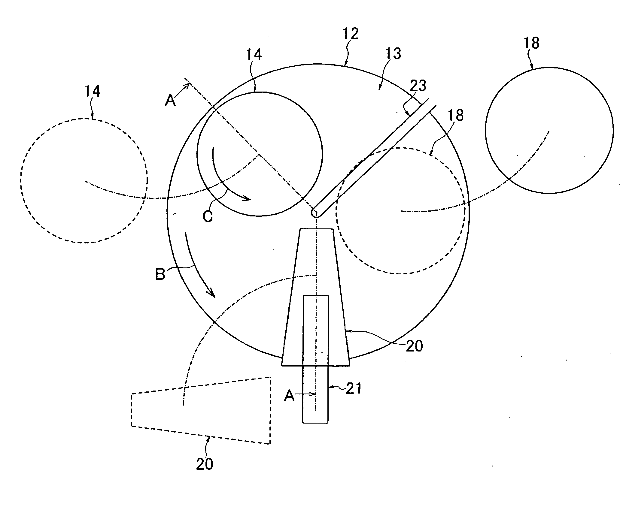
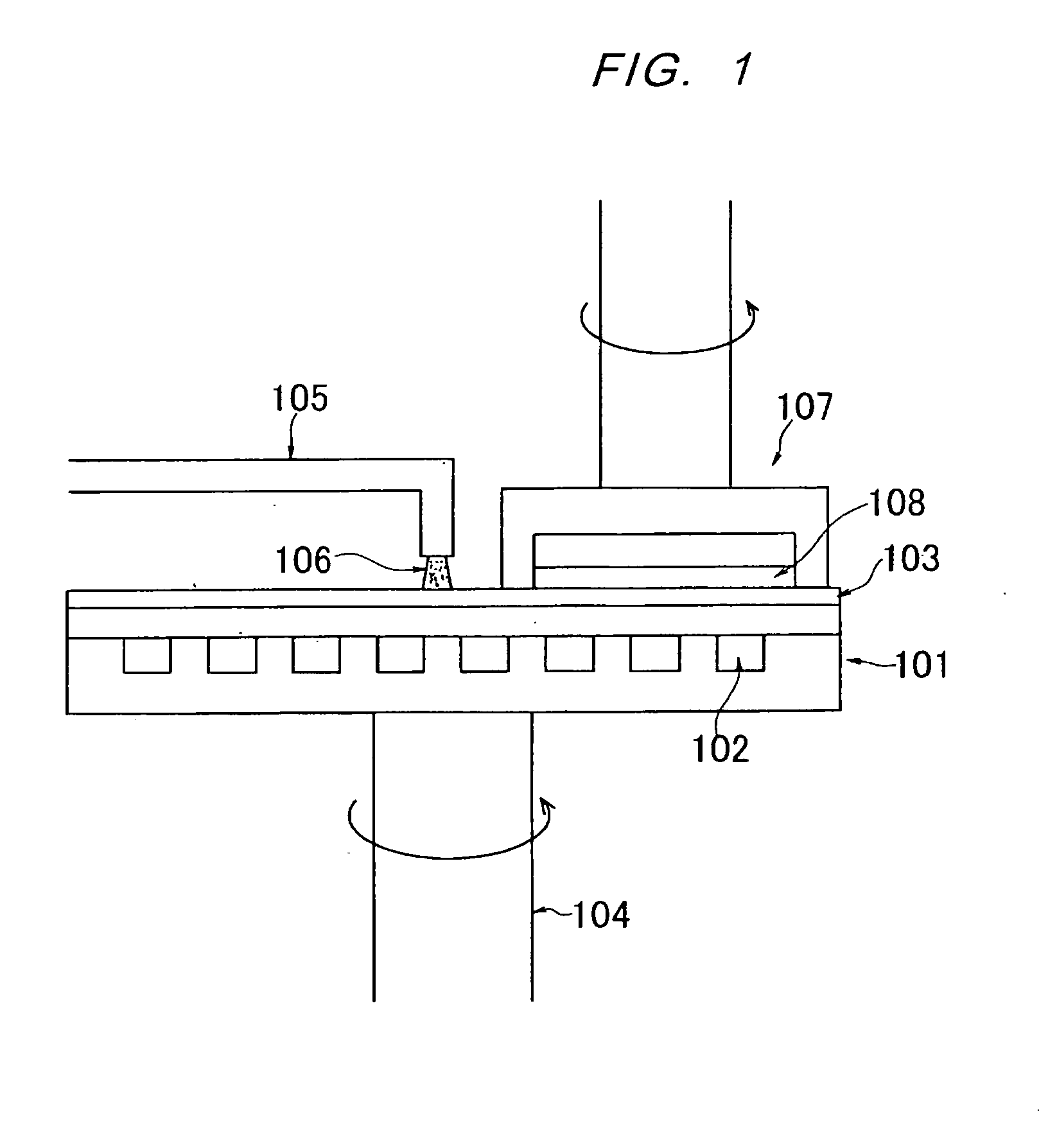
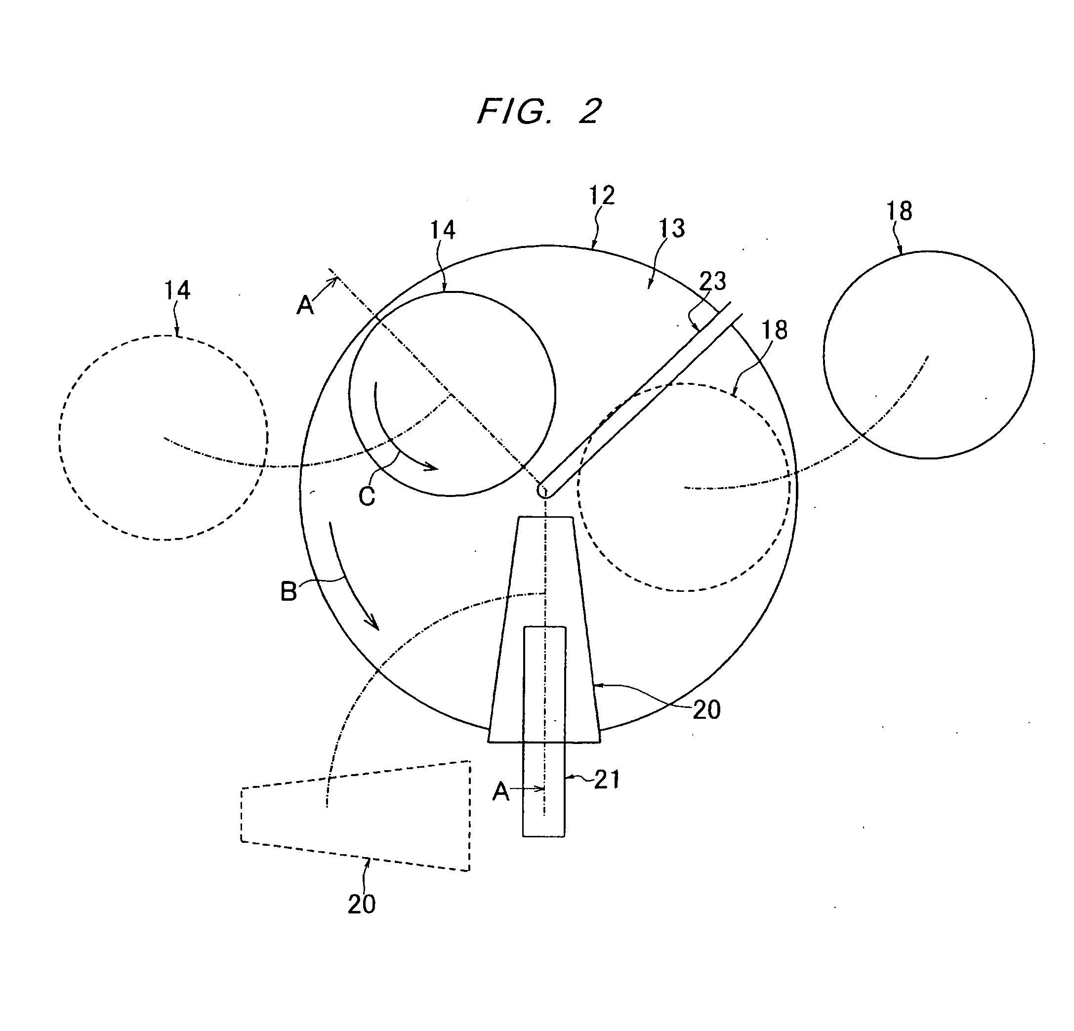
[0046]Embodiments of the present invention will be described below with reference to the drawings. FIG. 2 is a plan view showing a schematic structure of a polishing apparatus having an apparatus for heating or cooling a polishing surface according to an embodiment of the present invention. FIG. 3 is a cross-sectional view taken along line A-A in FIG. 2. The polishing apparatus 10 comprises a table 12 rotatable about a rotational shaft 11. A polishing pad 13 is attached to an upper surface of the table 12. Reference numeral 14 represents a workpiece-holding mechanism configured to hold a semiconductor wafer Wf, i.e., a workpiece to be polished. This workpiece-holding mechanism 14 is rotatably coupled to a holding-mechanism arm 16 via a rotational shaft 15. The holding-mechanism arm 16 has a rear end fixed to a swing shaft 17. Rotation of the swing shaft 17 allows the workpiece-holding mechanism 14 to move between a polishing position above the table 12 and a waiting position outward...


PUM

PropertyMeasurementUnit
surface temperatureaaaaaaaaaa

Abstract

The present invention provides an apparatus for heating or cooling a polishing surface. This apparatus includes a heat exchanger arranged so as to face the polishing surface when the workpiece is polished. The heat exchanger includes a medium passage through which a heat-exchanging medium flows, and a bottom surface facing the polishing surface. At least a part of the bottom surface is inclined with an upward gradient above the polishing surface such that a polishing liquid on the polishing surface generates a lift exerted on the bottom surface during movement of the polishing surface.

Description

BACKGROUND OF THE INVENTION[0001]1. Field of the Invention[0002]The present invention relates to an apparatus capable of heating or cooling a polishing surface of a polishing pad or fixed abrasive of a polishing apparatus for use in polishing various workpiece, such as a semiconductor wafer, various types of hard disk, a glass substrate, a liquid crystal panel, or the like.[0003]2. Description of the Related Art[0004]A CMP (Chemical Mechanical Polishing) apparatus has been used in fabrication processes of a semiconductor integrated circuit device. The CMP apparatus typically includes a holding mechanism for holding a semiconductor wafer (an object to be polished), and a rotatable table with a polishing pad or fixed abrasive attached thereto. The apparatus of this type is operable such that the holding mechanism presses the semiconductor wafer against a polishing surface of the polishing pad or fixed abrasive on the rotating table, while supplying a polishing liquid, e.g., slurry, on...

Claims


Application Information

Patent Timeline
Patent Type & Authority Applications(United States)
IPC IPC(8): B24B51/00B24B37/015H01L21/304
CPCB24B37/015B24B55/02H01L21/304
Inventor AIYOSHIZAWA, SHUNICHIKOSUGE, RYUICHIKATO, RYOISHII, YU
Owner EBARA CORP
Why Eureka
Try Eureka