Special-shaped workpiece drilling clamping table and use method thereof

A special-shaped workpiece and clamping technology, which is applied in the direction of boring/drilling, drilling/drilling equipment, metal processing machinery parts, etc., can solve the problems of low processing quality of special-shaped workpieces, unstable clamping, and potential safety hazards, etc. , to achieve the effect of shortening the clamping adjustment time, improving the processing quality, and improving the processing quality

Inactive Publication Date: 2020-11-27
太仓市双雄精工有限公司
View PDF8 Cites 0 Cited by
  • Summary
  • Abstract
  • Description
  • Claims
  • Application Information

AI Technical Summary

Problems solved by technology

[0002] In mechanical manufacturing, the device used to fix the processing object so that it occupies the correct position to accept construction or inspection is called a fixture; the use of fixtures can give full play to the potential of existing equipment and improve production efficiency; but the existing large Some of the fixtures are general-purpose fixtures. When using general-purpose fixtures to clamp special-shaped workpieces, the clamping is not stable enough, and there are potential safety hazards. At the same time, the impact force of processing will lead to low processing quality of special-shaped workpieces, prone to defective products, and high production costs.

Method used


Image

  • Special-shaped workpiece drilling clamping table and use method thereof
  • Special-shaped workpiece drilling clamping table and use method thereof
  • Special-shaped workpiece drilling clamping table and use method thereof

Examples


Embodiment Construction

[0025] In order to explain the overall concept of the present invention more clearly, the following will be described in detail by way of examples in conjunction with the accompanying drawings.

[0026] In describing the present invention, it is to be understood that the terms "center", "upper", "lower", "front", "rear", "left", "right", "vertical", "horizontal", The orientation or positional relationship indicated by "top", "bottom", "inner", "outer", "axial", "radial" and "circumferential" are based on the orientation or positional relationship shown in the drawings, only It is for the convenience of describing the present invention and simplifying the description, but does not indicate or imply that the referred device or element must have a specific orientation, be constructed and operated in a specific orientation, and thus should not be construed as limiting the present invention.

[0027] In addition, the terms "first" and "second" are used for descriptive purposes only...


PUM


Abstract

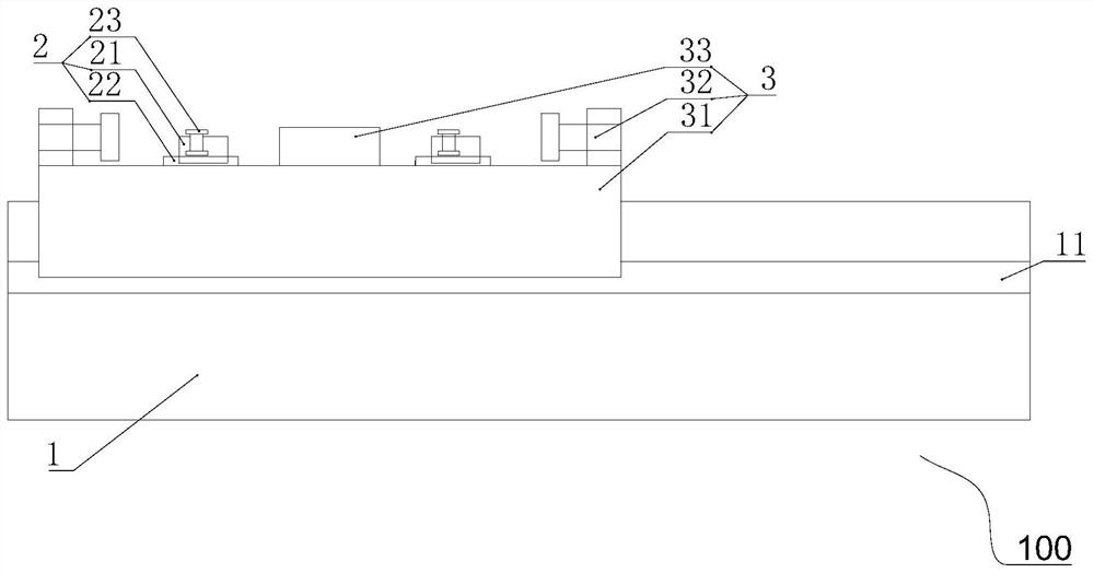
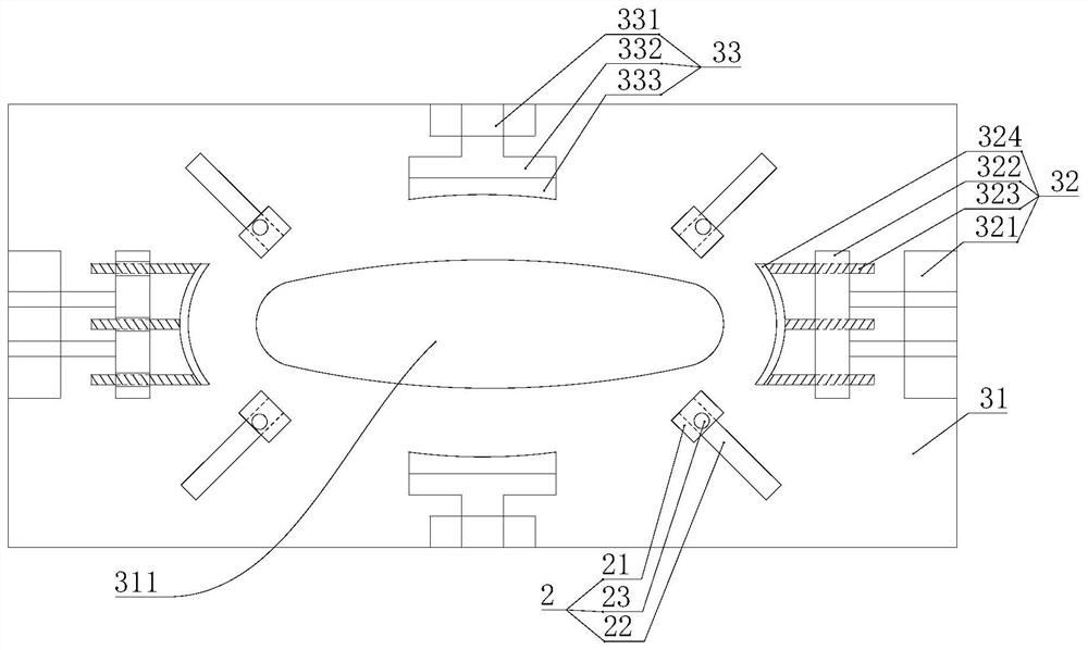
The invention discloses a special-shaped workpiece drilling clamping table and a use method thereof. The special-shaped workpiece drilling clamping table comprises a mounting base, a limiting assemblyand a clamping assembly. The clamping assembly is arranged at the top of the mounting base, and the clamping assembly comprises a clamping base, adjusting and fixing assemblies and extruding and fixing assemblies. A machining through hole is formed in the middle of the clamping base to reserve a machining position. The adjusting and fixing assemblies are oppositely arranged on the clamping base and located on the wide edges of the two sides of the clamping base. The extruding and fixing assemblies are oppositely arranged on the clamping base and located on the long edges of the two sides of the clamping base. The limiting assembly is arranged at the top of the clamping base to limit the clamping positions of workpieces. According to the special-shaped workpiece drilling clamping table andthe use method thereof, the limiting assembly is arranged and can quickly position the positions of the workpieces on the base; the adjusting and fixing assemblies can adapt to the workpieces with different sizes and radians, and meanwhile the adjusting and fixing assemblies can limit the longitudinal motion of the workpieces; and the transverse motion of the workpieces can be limited through theextruding and fixing assemblies, the machining stability is further improved, and the machining quality is effectively improved.

Description

technical field [0001] The invention belongs to the technical field of mechanical processing, and in particular relates to a special-shaped workpiece drilling fixture and a using method thereof. Background technique [0002] In mechanical manufacturing, the device used to fix the processing object so that it occupies the correct position to accept construction or inspection is called a fixture; the use of fixtures can give full play to the potential of existing equipment and improve production efficiency; but the existing large Some of the fixtures are general-purpose fixtures. When using general-purpose fixtures to clamp special-shaped workpieces, the clamping is not stable enough, and there are potential safety hazards. At the same time, the impact force of processing will lead to low processing quality of special-shaped workpieces, prone to defective products, and high production costs. . [0003] It should be noted that the above content belongs to the scope of the inve...

Claims


Application Information

Patent Timeline
Patent Type & Authority Applications(China)
IPC IPC(8): B23B41/00B23Q3/06
CPCB23B41/00B23Q3/062
Inventor 王建丰
Owner 太仓市双雄精工有限公司
Why Eureka
Try Eureka