Clamping device for welding robot

A welding robot and clamping device technology, which is applied in auxiliary devices, welding equipment, auxiliary welding equipment, etc., can solve problems such as difficult to clamp arc surface structure parts, limit the use range, etc., and achieve the effect of enhancing stability

Inactive Publication Date: 2020-11-27
NINGDE NORMAL UNIV
View PDF1 Cites 0 Cited by
  • Summary
  • Abstract
  • Description
  • Claims
  • Application Information

AI Technical Summary

Problems solved by technology

[0003] However, the above-mentioned technical solution still has the following disadvantages in actual use: it can only clamp parts with a square planar structure, and it is difficult to clamp parts with an arc surface structure, which limits the scope of use.

Method used


Image

  • Clamping device for welding robot
  • Clamping device for welding robot
  • Clamping device for welding robot

Examples


Embodiment 1

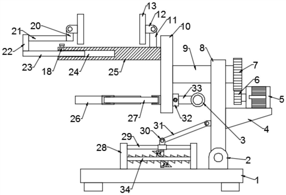
[0031] see Figure 1-5 , in an embodiment of the present invention, a clamping device for a welding robot includes a bottom plate 1, a turntable 10 is arranged on the upper side of the bottom plate 1, and a horizontal plate 25 is fixed on the turntable 10; Rod 11 and moving rod 20, fixed rod 11 is fixed on the horizontal plate 25, and horizontal plate 25 is provided with the adjusting assembly that is used to adjust the position of moving rod 20, and the fixed rod 11 and the moving rod 20 are hinged with the second support 12, A flat plate 13 is installed on the second support 12;

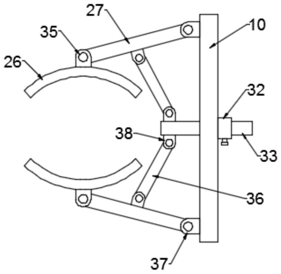
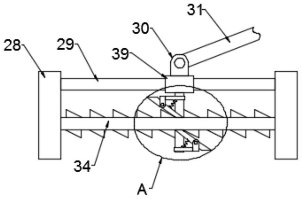
[0032] Two sixth supports 37 arranged symmetrically are installed on the turntable 10, the sixth support 37 is hinged with a push rod 27, and the end of the push rod 27 away from the sixth support 37 is hinged with a fifth support 35. The arc rod 26 is installed on the five support 35, and the pull-out assembly for driving the ejector rod 27 to rotate is arranged on the turntable 10; when in use, ...

Embodiment 2

[0044] see Figure 6 , in the embodiment of the present invention, a clamping device for a welding robot is different from Embodiment 1 in that a hydraulic cylinder 19 is provided on the cross bar 21, and a first sliding sleeve 17 is provided on the telescopic end of the hydraulic cylinder 19. , the first slide sleeve 17 is slidably provided with a slide bar 16, the slide bar 16 is hinged with a third support 15, and the bottom of the third support 15 is provided with a pressure plate 14; the first slide sleeve 17 is moved up and down by a hydraulic cylinder 19, And translate the slide bar 16, so that the pressing plate 14 is pressed on the upper part of the part to enhance the stability of the part.


PUM


Abstract

The invention is suitable for the technical field of welding robots and provides a clamping device for a welding robot. The clamping device comprises a bottom plate; a fixed rod and a movable rod arearranged on the upper side of a transverse plate; an adjusting component for adjusting the position of the movable rod is arranged on the transverse plate; second supports are hinged to the fixed rodand the movable rod; a flat plate is mounted on each of the second supports; two symmetrical sixth supports are mounted on a rotary disc; an ejector rod is hinged to each of the sixth supports; a fifth support is hinged to the end, far away from the sixth supports, of the ejector rod; an arc shaped rod is mounted on the fifth support; and a pulling component for driving the ejector rod to rotate is arranged on the rotary disc. According to the clamping device, a telescopic rod is moved in a slot to adjust the space between the two flat plates so as to clamp a square plane structure; and in addition, a pull rod is moved, and a second connecting rod drives the ejector rod to expand or shrink to enable the arc shaped rods to clamp a component with a cambered surface structure

Description

technical field [0001] The invention belongs to the technical field of welding robots, in particular to a clamping device for a welding robot. Background technique [0002] A clamping device for a welding robot is disclosed in the Chinese patent with the authorized notification number CN210476035U. The bottom inner wall of the box is provided with a push rod motor, and the output shaft of the push rod motor is fixedly connected with a vertical rod, and the right side of the vertical rod is fixed The first rack is connected, the front of the first rack is provided with a first gear, the inner fixed sleeve of the first gear is provided with a first rotating shaft, and the outer ring fixed sleeve at one end of the rotating shaft away from the first gear is provided with a second gear, the rotating shaft The outer ring is provided with a first bearing fixed on the inner wall of the top of the box, and the left side of the second gear is provided with a third gear. The parts can...

Claims


Application Information

Patent Timeline
Patent Type & Authority Applications(China)
IPC IPC(8): B23K37/04B23K37/047
CPCB23K37/0435B23K37/047
Inventor 缪海滔宋萌萌肖顺根
Owner NINGDE NORMAL UNIV
Why Eureka
Try Eureka