Unmanned vehicle brake control method, control system and vehicle
What is AI technical title?
AI technical title is built by Patsnap AI team. It summarizes the technical point description of the patent document.
An unmanned vehicle, brake control technology, applied in the direction of brake safety systems, brakes, vehicle components, etc., can solve problems such as unreasonable brake pressure configuration, avoid brake nodding and rollover accidents, and improve braking reliability Sexuality and driving safety, and the effect of extending the service life
Active Publication Date: 2022-05-31
上海易咖智车科技有限公司
View PDF5 Cites 0 Cited by
Summary
Abstract
Description
Claims
Application Information
AI Technical Summary
This helps you quickly interpret patents by identifying the three key elements:
Problems solved by technology
Method used
Benefits of technology
Problems solved by technology
[0005] The invention provides a braking control method for an unmanned vehicle, which solves the problem of unreasonable braking pressure configuration and is beneficial to improving braking reliability
Method used
Image
Click on the blue label to locate the original text in one second.
Reading with bidirectional positioning of images and text.
Examples
Embodiment 1
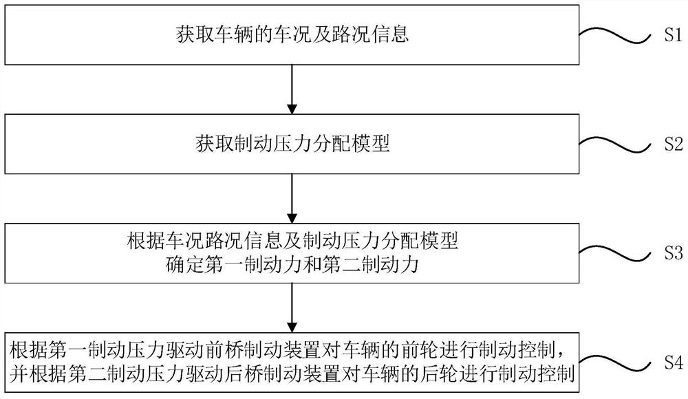
[0038] FIG. 1 is a flowchart of a method for controlling the braking of an unmanned vehicle provided by Embodiment 1 of the present invention. This implementation
[0039] Step S1: obtain the vehicle condition and road condition information of the vehicle.
[0041] Step S2: obtain the brake pressure distribution model.
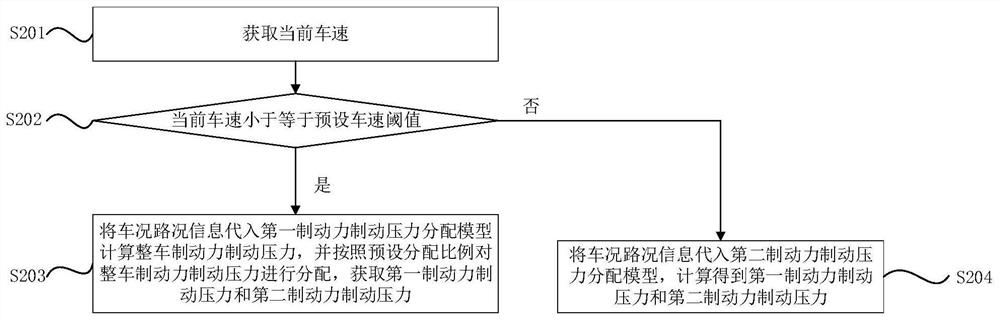
[0052] FIG. 2 is a flowchart of another unmanned vehicle braking control method provided by Embodiment 1 of the present invention.
[0054] Step S201: obtain the current vehicle speed.
[0055] Step S202: judging whether the current vehicle speed is less than or equal to a preset vehicle speed threshold.
[0056] If yes, then execute step S203; otherwise, execute step S204.
[0062] Exemplarily, the preset distribution ratio a:b can be set to be equal to 4:6.
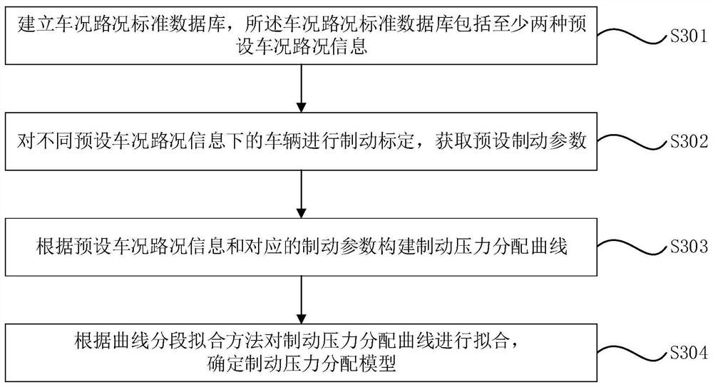
[0066] FIG. 3 is a flowchart of another unmanned vehicle braking control method provided by Embodiment 1 of the present invention.
[0067] Optionally, obtain the brake pressure distribution model, including...
Embodiment 2
[0125] The embodiment of the present invention also provides an unmanned vehicle braking control system. Fig. 6 is the second embodiment of the present invention
[0127] Optionally, as shown in FIG. 6 and FIG. 7, the front axle braking device 50 includes: a first motor 501, a first hydraulic cylinder 503 and
[0128] Wherein, the first motor 501 and the second motor 601 can be brushless servo motors, the first brake controller 30, the second motor
Embodiment 3
[0140] Embodiment 3 of the present invention also provides a vehicle. Fig. 8 is a structure of a vehicle provided by the third embodiment of the present invention
PUM
Abstract
The invention discloses a braking control method, a control system and a vehicle for an unmanned vehicle. The braking control method comprises the following steps: acquiring vehicle condition and road condition information of the vehicle; acquiring a brake pressure distribution model; The pressure distribution model determines the first brake pressure and the second brake pressure; drives the front axle brake device to brake the front wheels according to the first brake pressure, and drives the rear axle brake device to brake the front wheels according to the second brake pressure Rear wheel brake control. The brake control method provided by the embodiment of the present invention can customize the brake pressure distribution of the front axle and the rear axle according to the vehicle condition and road condition information, which solves the problem of unreasonable brake pressure configuration and avoids brake nodding and In the event of a rollover accident, it ensures a stable braking posture of the vehicle body, which helps to prolong the service life of the vehicle's braking device. In addition, it can solve the braking problem under some extreme working conditions, which is conducive to improving braking reliability and driving safety.
Description
Unmanned vehicle braking control method, control system and vehicle technical field The present invention relates to the technical field of braking control, in particular to a kind of unmanned vehicle braking control method, control systems and vehicles. Background technique [0002] With the development of unmanned technology, unmanned vehicles are used in the fields of logistics transportation, ferrying passengers, and emergency rescue. has been more and more widely used. At present, the braking scheme of unmanned vehicle mainly adopts traditional hydraulic braking scheme or pneumatic braking method. In the traditional hydraulic braking scheme, a brake master cylinder is usually set, and the brake master cylinder is connected to each hydraulic circuit through a hydraulic circuit. Press the brake, control the action of the brake master cylinder by collecting the brake pedal signal, and adjust the braking pressure of each hydraulic brake; The working principle of t...
Claims
Application Information
Patent Timeline
Application Date:The date an application was filed.
Publication Date:The date a patent or application was officially published.
First Publication Date:The earliest publication date of a patent with the same application number.
Issue Date:Publication date of the patent grant document.
PCT Entry Date:The Entry date of PCT National Phase.
Estimated Expiry Date:The statutory expiry date of a patent right according to the Patent Law, and it is the longest term of protection that the patent right can achieve without the termination of the patent right due to other reasons(Term extension factor has been taken into account ).
Invalid Date:Actual expiry date is based on effective date or publication date of legal transaction data of invalid patent.

