Positive-pressure slag cooling system for biomass fluidized bed gasifier

A technology of fluidized bed gasification furnace and biomass, applied in the field of positive pressure cold slag system, can solve the problems of leakage of harmful gas in ash slag, inability to ensure sealing, gasification furnace gas leakage, etc., to achieve convenient transportation slag, prevent leakage, and prevent deflagration accidents

Inactive Publication Date: 2020-11-27
HARBIN BOILER
View PDF8 Cites 2 Cited by
  • Summary
  • Abstract
  • Description
  • Claims
  • Application Information

AI Technical Summary

Problems solved by technology

[0004] The purpose of the present invention is to solve the problem that the existing slag cooling system only has the ability to cool slag, but cannot guarantee the sealing, and there is a risk of leakage of gas produced by the gasifier, resulting in the leakage of harmful gas in the ash, and further provides a Positive pressure cold slag system for biomass fluidized bed gasifier

Method used


Image

  • Positive-pressure slag cooling system for biomass fluidized bed gasifier

Examples


specific Embodiment approach 1

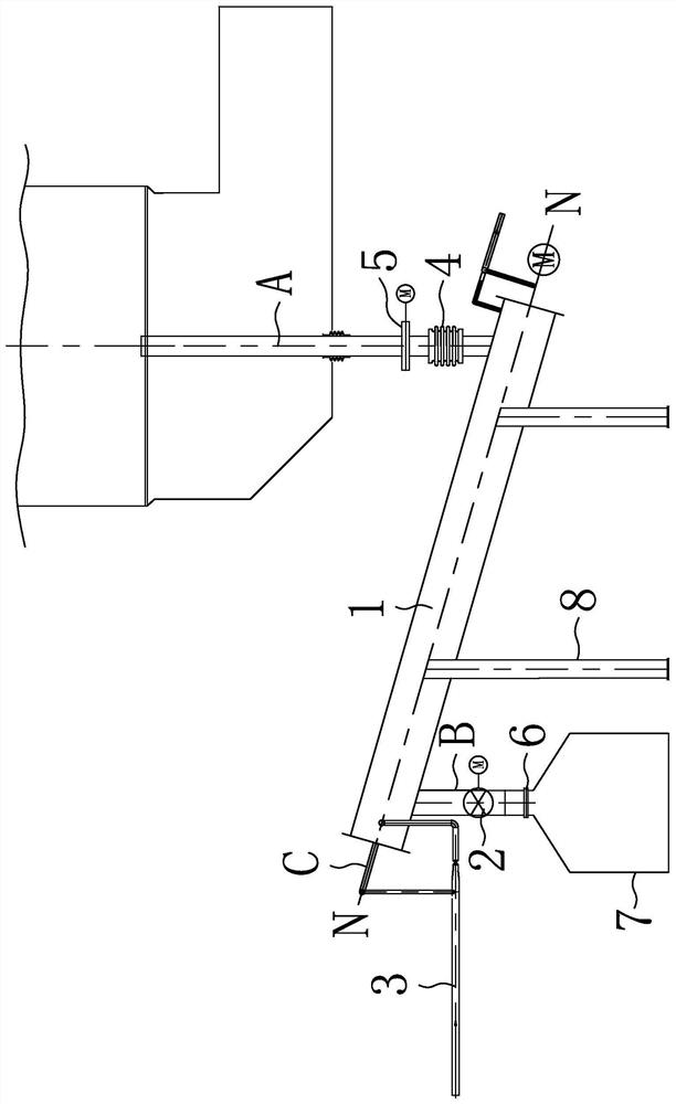
[0016] Specific implementation mode one: combine figure 1 Describe this embodiment, a positive pressure slag cooling system for a biomass fluidized bed gasifier in this embodiment, which includes a spiral slag cooler 1, a cooling water system 3, an electric ram door 5, a manual ram The door 6, the slag storage tank 7 and the support 8, the spiral slag cooler 1 are arranged obliquely, the support 8 is arranged under the spiral slag cooler 1, the spiral slag cooler 1 is connected to the upper end of the support 8, and the lower end of the spiral slag cooler 1 is connected to the gasification The lower end of the slag discharge pipe A of the furnace is connected, and an electric gate 5 is provided under the slag discharge pipe A. The upper end of the spiral slag cooler 1 is connected to the upper end of the ash outlet pipe B, and the lower end of the ash outlet pipe B is connected to the slag storage tank 7. The ash outlet pipe B is provided with a rotary sealing valve 2, and the...

specific Embodiment approach 2

[0018] Specific implementation mode two: combination figure 1 Describe this embodiment, this embodiment also includes a compensator 4, and the compensator 4 is arranged on the slag discharge pipeline A between the electric gate 5 and the spiral slag cooler 1 . So set, the expansion between the slag discharge pipe and the slag cooler 1 is absorbed by the compensator 4 . Other compositions and connections are the same as in the first embodiment.

specific Embodiment approach 3

[0019] Specific implementation mode three: combination figure 1 To describe this embodiment, the included angle between the axis N-N of the spiral slag cooler 1 of this embodiment and the horizontal plane is 10-25°. In this way, the spiral slag cooler 1 arranged obliquely can prevent the positive pressure gas in the furnace from going back and play a sealing effect. Other compositions and connections are the same as those in Embodiment 1 or Embodiment 2.

[0020] Specific implementation mode four: combination figure 1 To describe this embodiment, the included angle between the axis N-N of the spiral slag cooler 1 of this embodiment and the horizontal plane is 16°. In this way, the spiral slag cooler 1 arranged obliquely can prevent the positive pressure gas in the furnace from going back and play a sealing effect. Other compositions and connections are the same as those in Embodiment 1, 2 or 3.

[0021] Specific implementation mode five: combination figure 1 To illustrate...


PUM


Abstract

A positive-pressure slag cooling system for a biomass fluidized bed gasification furnace relates to the field of biomass gasifiers. The slag cooling system solves the problems that an existing slag cooling system only has the slag cooling capacity, the sealing performance cannot be guaranteed, the risk of gas production leakage of a gasifier exists, and harmful gas in ash leaks out. The spiral slag cooler is obliquely arranged; a bracket is arranged below the spiral slag cooler; the spiral slag cooler is connected with the upper end of the bracket; the lower end of the spiral slag cooler is connected with the lower end of a deslagging pipeline of the gasifier; an electric flashboard door is arranged below the deslagging pipeline; the upper end of the spiral slag cooler is connected with the upper end of an ash outlet pipeline; the lower end of the ash outlet pipeline is connected with an ash storage tank; a rotary sealing valve is arranged on the ash outlet pipeline; a manual flashboard door is arranged on the ash outlet pipeline between the rotary sealing valve and the ash storage tank; the cooling water system penetrates through the interior of the spiral ash cooler; and a cooling water pipeline of the cooling water system is in sealing fit with the spiral ash cooler. The system is used for preventing gas generated by the gasifier from leaking and realizing positive-pressureslag cooling.

Description

technical field [0001] The invention relates to the field of biomass gasification furnaces, in particular to a positive pressure cold slag system for a biomass fluidized bed gasification furnace. Background technique [0002] The gas produced by biomass gasification has a high calorific value and can be developed and utilized as high-quality energy after purification treatment to meet the quality requirements of industrial production and domestic gas. The biomass gasifier is the main equipment of the gasification device. The slag discharge temperature is as high as 800°C, which cannot be discharged directly, and the sensible heat of slag cannot be recovered. The conventional slag cooling system only has the ability to cool slag, but it cannot guarantee the sealing. There is a risk of gasifier gas leakage, resulting in the leakage of harmful gas in the ash. [0003] To sum up, the existing slag cooling system only has the ability to cool slag, but it cannot guarantee the sea...

Claims


Application Information

Patent Timeline
Patent Type & Authority Applications(China)
IPC IPC(8): C10J3/56C10J3/72F25D17/02
CPCC10J3/56C10J3/72C10J2300/0916F25D17/02
Inventor 朱英伟孙向文王君峰姜孝国
Owner HARBIN BOILER
Why Eureka
Try Eureka