Active comprehensive load reduction structure and method for high-fill roadbed culvert

A high-filling and active technology, applied in infrastructure engineering, roads, roads, etc., can solve problems such as cracking, limited engineering effects, separation and cracking of culvert roofs and walls, etc., to reduce the concentration of earth pressure and improve the impact Force asymmetry, the effect of solving the cracking phenomenon

Active Publication Date: 2020-11-27
CHINA UNIV OF GEOSCIENCES (WUHAN)
View PDF7 Cites 1 Cited by
  • Summary
  • Abstract
  • Description
  • Claims
  • Application Information

AI Technical Summary

Problems solved by technology

Although the above methods are widely used, the actual engineering effect is limited. The cracking of the culvert roof and side wall, and the asymmetrical force on the cu

Method used


Image

  • Active comprehensive load reduction structure and method for high-fill roadbed culvert
  • Active comprehensive load reduction structure and method for high-fill roadbed culvert
  • Active comprehensive load reduction structure and method for high-fill roadbed culvert

Examples


Embodiment Construction

[0033] In order to make the purpose, technical solution and advantages of the present invention clearer, the embodiments of the present invention will be further described below in conjunction with the accompanying drawings.

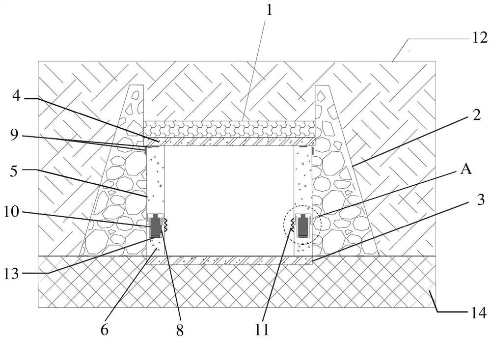
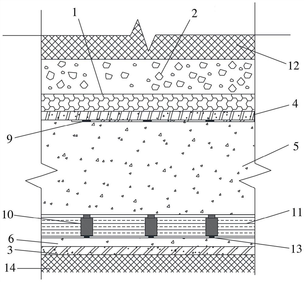
[0034] See Figure 1 to Figure 4 , The embodiment of the present invention provides an active comprehensive load-reducing structure of a high-fill subgrade culvert, including a culvert, a load-reducing groove 1, an earth-stone side wall 2, and a pressurized adaptive system.

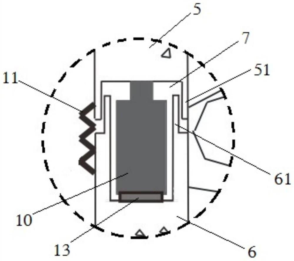
[0035] See Figure 1 to Figure 3 , the culvert is located on the foundation 14, including the culvert base plate 3, the culvert side wall and the culvert cover plate 4 located at the two ends of the culvert base plate 3, the culvert side wall includes an upper wall 5 and a lower wall 6, and the lower wall 6 Fixed on the base plate 3 of the culvert, the upper wall 5 is located above the lower wall 6 and forms an accommodating space 7 with the lower wall 6, and the upper wall 5 can b...


PUM


Abstract

The invention provides an active comprehensive load reduction structure and method for a high-fill roadbed culvert. The load reduction structure comprises a culvert, a load reduction groove and a pressurization type self-adaptive system. The culvert is arranged on a foundation and comprises a culvert base plate, culvert side walls arranged at the two ends of the culvert base plate and a culvert cover plate. The load reduction groove is fixed to the top of the culvert cover plate, and the load reduction groove is filled with a light flexible material. Earth-stone side walls are arranged on thetwo sides of the culvert correspondingly, and the tops of the earth-stone side walls protrude out of the load reduction groove. The pressurization type self-adaptive system comprises a single-chip microcomputer, a plurality of pressure sensors and a plurality of jacking and stretching devices. The single-chip microcomputer is arranged in the culvert, and the multiple pressure sensors are arrangedat the position where stress on the top of the culvert is concentrated and electrically connected with the single-chip microcomputer. The jacking and stretching devices are electrically connected withthe single-chip microcomputer and used for initial jacking of the bottom of the upper wall and later stress adjustment. The technical scheme provided by the invention has the beneficial effects thata load reduction effect is obvious, acontrollable stress of the culvert can be realized, and data support is provided for scientific research in related fields.

Description

technical field [0001] The invention relates to the technical field of highway engineering, in particular to an active comprehensive load-reducing structure and a load-reducing method for high-fill embankment culverts. Background technique [0002] High-fill subgrade is an important basic form in the construction of mountain roads. In order to take into account the functions of traffic and drainage, culverts are often set at the bottom. The backfill soil on the top of the above-mentioned culverts is usually more than 10m, has a large self-weight, and gradually produces uneven settlement, which leads to significant stress concentration in the high-fill subgrade culverts, and then produces various degrees of diseases such as cracking, water seepage, and even structural damage. It has been applied in practical engineering to reduce the vertical earth pressure on the culvert top of high fill culverts through load reduction measures to reduce the structural damage of culverts. ...

Claims


Application Information

Patent Timeline
IPC IPC(8): E01F5/00E01C3/00E02D1/00E01C3/06
CPCE01C3/00E01C3/06E01F5/005E02D1/00
Inventor 马俊伟张俊荣牛晓旭刘晓
Owner CHINA UNIV OF GEOSCIENCES (WUHAN)
Why Eureka
Try Eureka