
Assembly type prefabricated beam and column connecting joint and construction method

A beam-column connection and prefabricated technology, which is applied in the direction of architecture and building construction, can solve problems such as the difficulty of beam-column joint connection, and achieve the effects of clear and reasonable force transmission mechanism, accelerated construction speed, and good cohesion

Inactive Publication Date: 2020-11-27
HEBEI UNIV OF TECH
View PDF13 Cites 5 Cited by
  • Summary
  • Abstract
  • Description
  • Claims
  • Application Information

AI Technical Summary

Problems solved by technology

[0014] The purpose of the present invention is to overcome the deficiencies of the prior art and provide a prefabricated prefabricated beam-column connection node and construction method. Technical Problems of Difficult Connection of Beam-column Joints in Concrete Frame Structures

Method used


Image

  • Assembly type prefabricated beam and column connecting joint and construction method
  • Assembly type prefabricated beam and column connecting joint and construction method
  • Assembly type prefabricated beam and column connecting joint and construction method

Examples


Embodiment 1

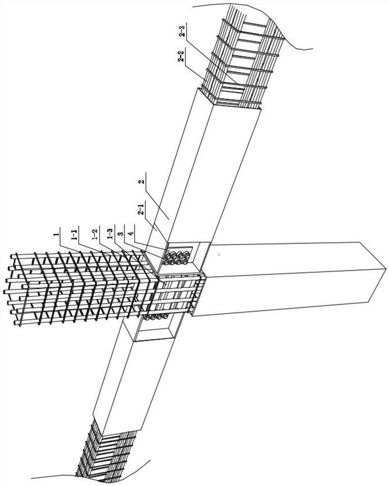
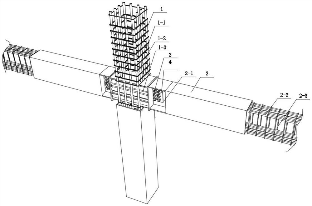
[0049] An assembled prefabricated beam-column connection node includes a prefabricated column 1 and two prefabricated beams 2, and the prefabricated beam and the prefabricated column are fixedly connected by a pre-embedded H-shaped steel 2-1 at one end of the prefabricated beam. In this embodiment, both sides of the prefabricated column are connected to a prefabricated beam respectively; The specific structure of the connection node is as follows:

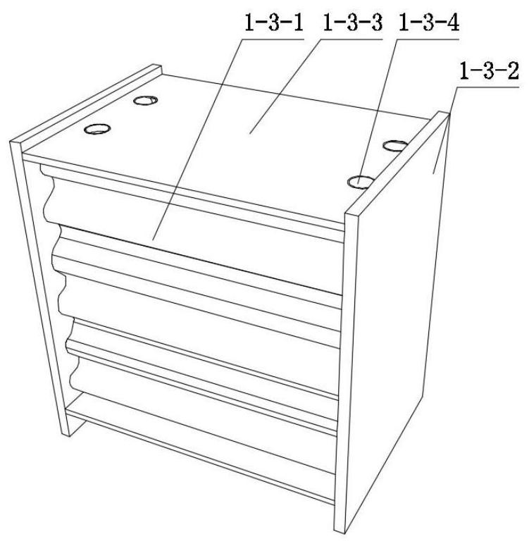
[0050] The prefabricated column includes a column internal longitudinal reinforcement 1-1, a column internal stirrup 1-2 and a column internal embedded part 1-3, the column internal stirrup is located outside the column internal longitudinal reinforcement, and the column internal The parts are fixed in position by interspersing and bundling the stirrups in the column and the longitudinal bars in the column. The embedded parts in the column include corrugated steel 1-3-1 and steel plate 1-3-2 on the side of the column. The two ends ...

Embodiment 2

[0065] An assembled prefabricated beam-column connection node, including a prefabricated column and four prefabricated beams, the four sides of the prefabricated column are respectively connected to a prefabricated beam at the same time, the specific details of the connection node between the end of the prefabricated beam and the side of the prefabricated column The structure is as follows:

[0066] The prefabricated column includes the longitudinal reinforcement in the column, the stirrup in the column and the embedded part in the column. The stirrup in the column is located outside the longitudinal reinforcement in the column. The interspersed binding of the longitudinal reinforcement realizes the limit fixation. The embedded parts in the column are the embedded parts 1-4 in the well-shaped column or the embedded parts 1-5 in the cross-shaped column. The embedded parts include well-shaped corrugated steel and four column-side steel plates 1-4-2, and the well-shaped corrugate...


PUM


Abstract

The invention relates to an assembly type prefabricated beam and column connecting joint. The joint comprises a prefabricated column and prefabricated beams; the prefabricated column comprises in-column longitudinal bars, in-column stirrups and in-column embedded parts; the prefabricated beams comprise in-beam longitudinal bars, in-beam stirrups and embedded H-shaped steel; and during on-site construction, beam and column connecting steel sheets are welded to the end faces of the in-column embedded parts of the prefabricated column, and the prefabricated beams are externally connected with theend faces of the in-column embedded parts of the prefabricated column through the end of the embedded H-shaped steel and are in bolted connection with the beam and column connecting steel sheets. Theinvention further provides a construction method of the assembly type prefabricated beam and column connecting joint. According to the joint and the method, the construction is easy, the stress performance of the connecting position is excellent, the rigidity is high, and the technical problem of difficult connection of a beam and column joint in an assembly type concrete frame structure is solved.

Description

technical field [0001] The invention belongs to the technical field of building structures, and relates to an assembled beam-column joint technology, in particular to an assembled prefabricated beam-column joint and a construction method. Background technique [0002] With the rapid development of my country's economy, people's living standards continue to improve, and the requirements for housing are increasing. At the same time, the cast-in-place construction method of residential buildings is not compatible with the concept of sustainable development in my country. At present, my country urgently needs to solve the problems of high energy consumption, high pollution, and high investment in residential construction. Therefore, the Ministry of Housing and Urban-Rural Development of the Development and Reform Commission of my country has promulgated the "Green Building Action Plan", which clearly mentions the promotion of prefabricated assembly suitable for industrial produc...

Claims


Application Information

Patent Timeline
Patent Type & Authority Applications(China)
IPC IPC(8): E04B1/21
CPCE04B1/21E04B1/215
Inventor 戎贤张健新杨洪渭石晓娜刘平李艳艳
Owner HEBEI UNIV OF TECH
Learn More