Guide rail type mobile switch cabinet partial discharge on-line monitoring sensor
A technology for monitoring sensors and moving switches, which is applied to the components of electrical measuring instruments, instruments, and measuring electronics. It can solve the problems of complex structure, time-consuming and labor-intensive detection process of switch cabinet partial discharge, etc., and achieve the effect of quick installation and disassembly.
- Summary
- Abstract
- Description
- Claims
- Application Information
AI Technical Summary
Problems solved by technology
Method used
Image
Examples
Embodiment 1
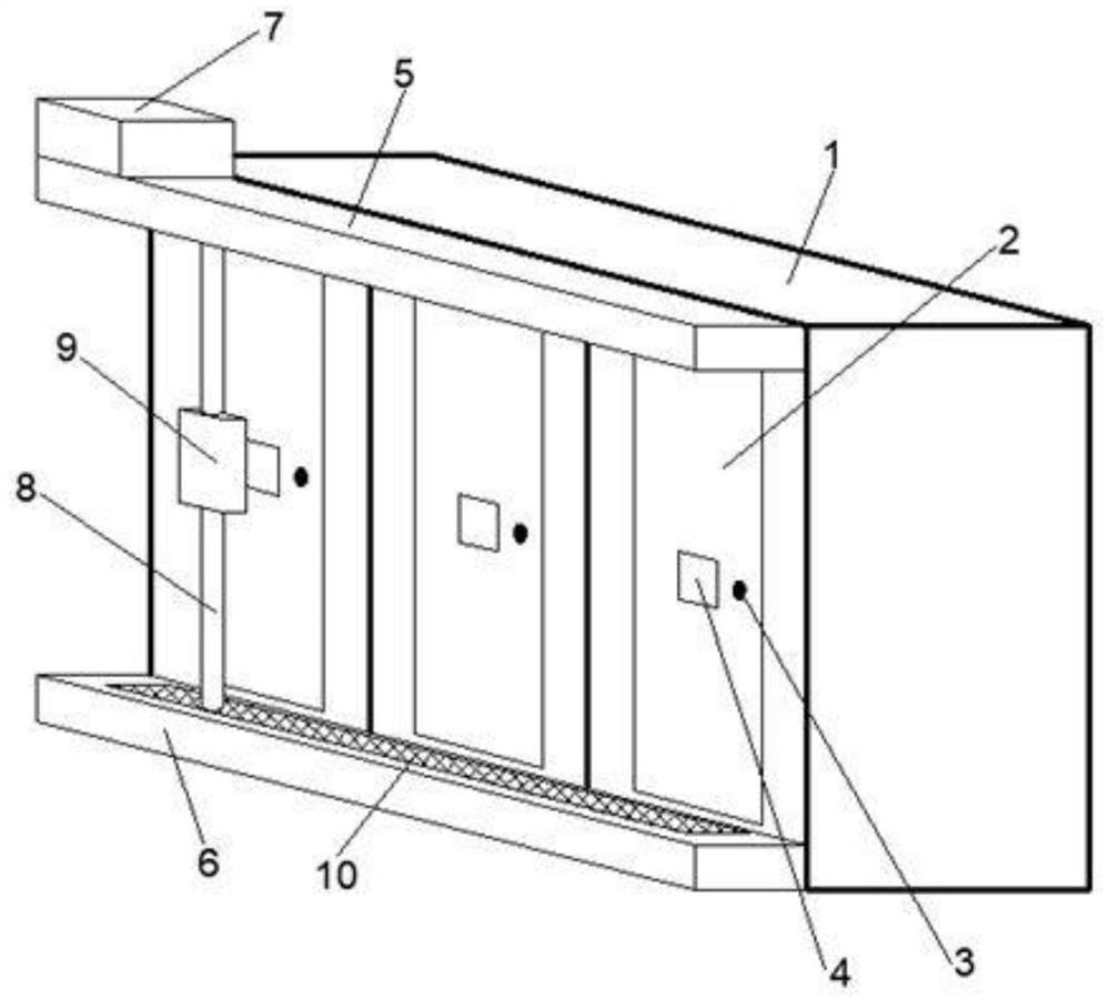
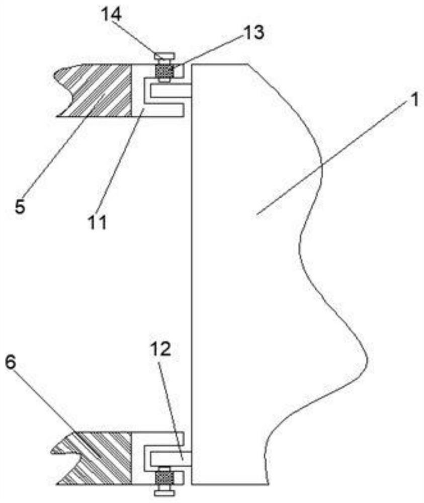
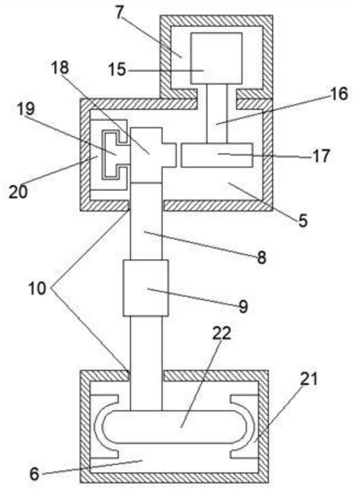
[0029] refer to Figure 1-4 , a guide rail type mobile switchgear local on-line monitoring sensor, including a switchgear 1, a monitoring device 9, a first operating device and a second operating device, the front of the switchgear 1 is fixedly installed with a cabinet door 2, and the middle part of the cabinet door 2 is provided with a The opening 4, the right side of the cabinet door 2 is provided with a handle 3, the upper and lower ends of the front of the switch cabinet 1 are fixedly connected with the clip board 12, the first running device includes the first track 5 and the second track 6, the first track 5 and the The back of the second track 6 is fixedly connected with a clip groove 11, the clip groove 11 is in contact with the clip plate 12, and the outer surface of the clip groove 11 is provided with a plurality of groups of threaded holes 13, and the threaded holes 13 are threadedly connected with screws 14. One end of the upper surface of a track 5 is fixedly equi...
Embodiment 2
[0035] refer to Figure 5 The difference in connection with the basis of Embodiment 1 is that the monitoring device 9 includes a rod outlet 24, a first baffle plate 25, an extension pipe 31 and a connecting rod 36, and the rod outlet 24 is arranged on the upper right side of the monitoring device 9 , the side of the first baffle plate 25 is fixedly connected with the first slide bar 29, the first slide bar 29 is slidably connected with the first chute 28, the first chute 28 is fixedly installed on the inner wall of the lower end of the right side of the monitoring device 9, the first baffle plate The lower end of 25 is provided with a magnet 26, and the right side of the lower end of the inner wall of the monitoring device 9 is provided with an electromagnet 27. The outer surface of the extension pipe 31 is movably socketed with the inside of the support sleeve 30, and the lower surface of the support sleeve 30 is fixedly connected with one end of the first support rod 32. The...
Embodiment 3
[0039] refer to Figure 6 and 7 The difference in connection with the basis of Embodiment 1 is that the cabinet door 2 includes a second chute 44, a clamp groove 46 and a contact block 48, and the contact block 48 is fixedly installed on the outside of the cabinet door 2, and the contact block 48 is arranged on the The upper end of the port 4, the second chute 44 is fixedly installed on the inner side of the cabinet door 2, the second chute 44 is set on the upper end of the port 4, the clamping slot 46 is fixedly connected to the inner side of the cabinet door 2, and the clamping slot 46 is set on the opening 4. At the lower end, the card slot 46 is provided with a card port 47, and the second chute 44 is slidably connected with the second slide bar 43. The second slide bar 43 is fixedly connected to the top of the second baffle plate 45, and the second baffle plate 45 The upper part of the other side plate surface is fixedly connected with a gear bar 42, the gear bar 42 is m...
PUM
 Abstract
Description
Claims
Application Information
 - R&D
- Intellectual Property
- Life Sciences
- Materials
- Tech Scout
- Unparalleled Data Quality
- Higher Quality Content
- 60% Fewer Hallucinations
Browse by: Latest US Patents, China's latest patents, Technical Efficacy Thesaurus, Application Domain, Technology Topic, Popular Technical Reports.
© 2025 PatSnap. All rights reserved.Legal|Privacy policy|Modern Slavery Act Transparency Statement|Sitemap|About US| Contact US: help@patsnap.com


