AI technical title is built by Patsnap AI team. It summarizes the technical point description of the patent document.
A grinding machine and machine base technology, which is applied in the direction of grinding frames, grinding machine parts, grinding/polishing equipment, etc., can solve problems such as damage to grinding blocks, and achieve the effect of avoiding damage.
Active Publication Date: 2021-12-14
泉州台商投资区源祺工业设计有限公司
View PDF6 Cites 0 Cited by
Summary
Abstract
Description
Claims
Application Information
AI Technical Summary
This helps you quickly interpret patents by identifying the three key elements:
Problems solved by technology
Method used
Benefits of technology
Problems solved by technology
[0003] When the existing floor polisher is working, since the ground may protrude with steel pipes or hard debris, if the floor polisher is moving, if you do not pay attention, it is easy to make the module contact with it for hard friction, causing damage to the grinding block. damage
Method used
Image
Click on the blue label to locate the original text in one second.
Reading with bidirectional positioning of images and text.
Examples
Embodiment 1
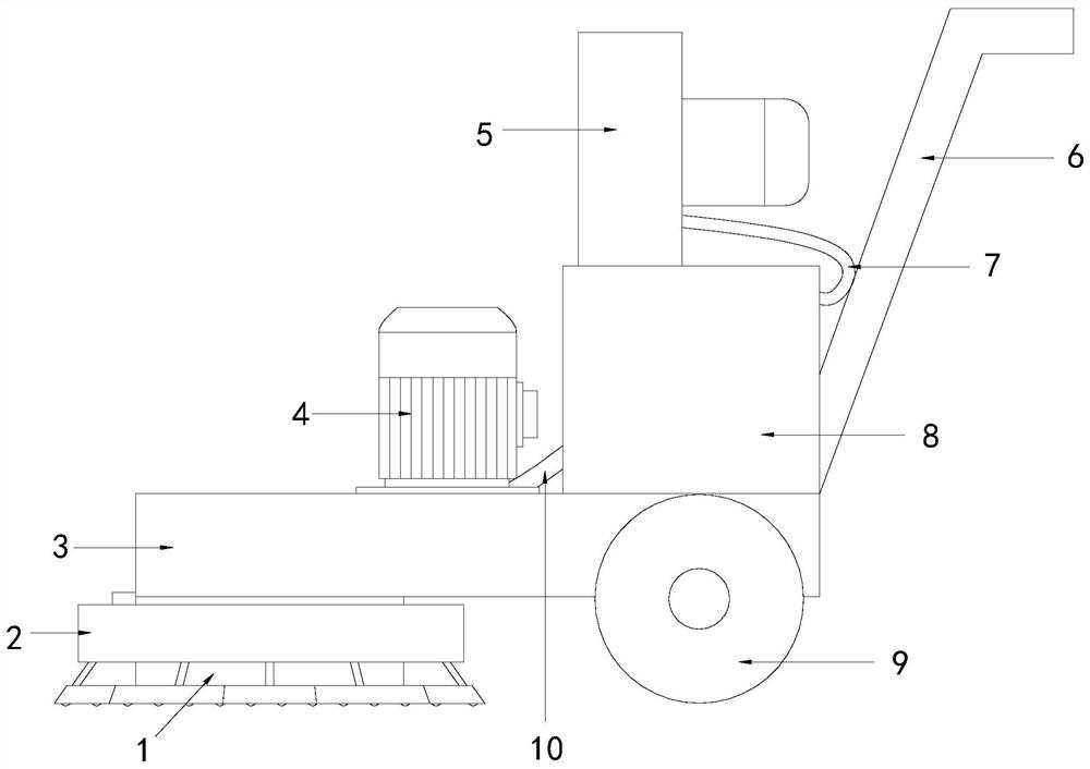
[0028] see Figure 1-5 , the present invention provides a floor polisher technical solution: its structure includes a vacuum cover 1, a reminder device 2, a machine base 3, a motor 4, a fan 5, a handrail 6, a first air duct 7, a dust box 8, Moving wheel 9, the second air duct 10, one end of the bottom of the base 3 is connected with a dust cover 1, the dust cover 1 is provided with a grinding block, and the other end of the base 3 is equipped with a moving wheel 9, so Described handrail 6 is located at the top of moving wheel 9 and is connected with support 3, and described support 3 is connected with motor 4, dust collection box 8, and described motor 4 is connected with grinding block transmission, and described dust collection box 8 passes through The second air duct 10 communicates with the dust collection hood 1, the fan 5 is connected to the top of the dust collection box 8 and communicates with the dust collection box 8 through the first air duct 7, and a reminder devic...
Embodiment 2
[0031] see Figure 1-5, the present invention provides a floor polisher technical solution: its structure includes a vacuum cover 1, a reminder device 2, a machine base 3, a motor 4, a fan 5, a handrail 6, a first air duct 7, a dust box 8, Moving wheel 9, the second air duct 10, one end of the bottom of the base 3 is connected with a dust cover 1, the dust cover 1 is provided with a grinding block, and the other end of the base 3 is equipped with a moving wheel 9, so Described handrail 6 is located at the top of moving wheel 9 and is connected with support 3, and described support 3 is connected with motor 4, dust collection box 8, and described motor 4 is connected with grinding block transmission, and described dust collection box 8 passes through The second air duct 10 communicates with the dust collection hood 1, the fan 5 is connected to the top of the dust collection box 8 and communicates with the dust collection box 8 through the first air duct 7, and a reminder device...
PUM
Abstract
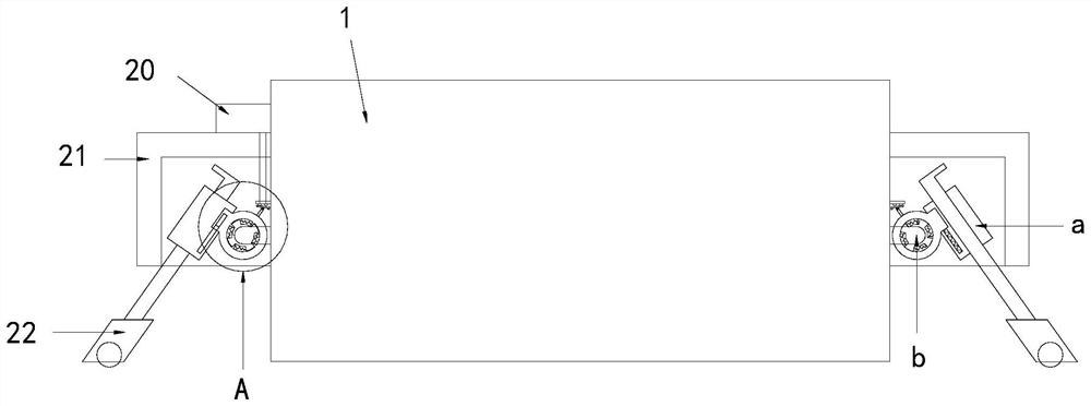
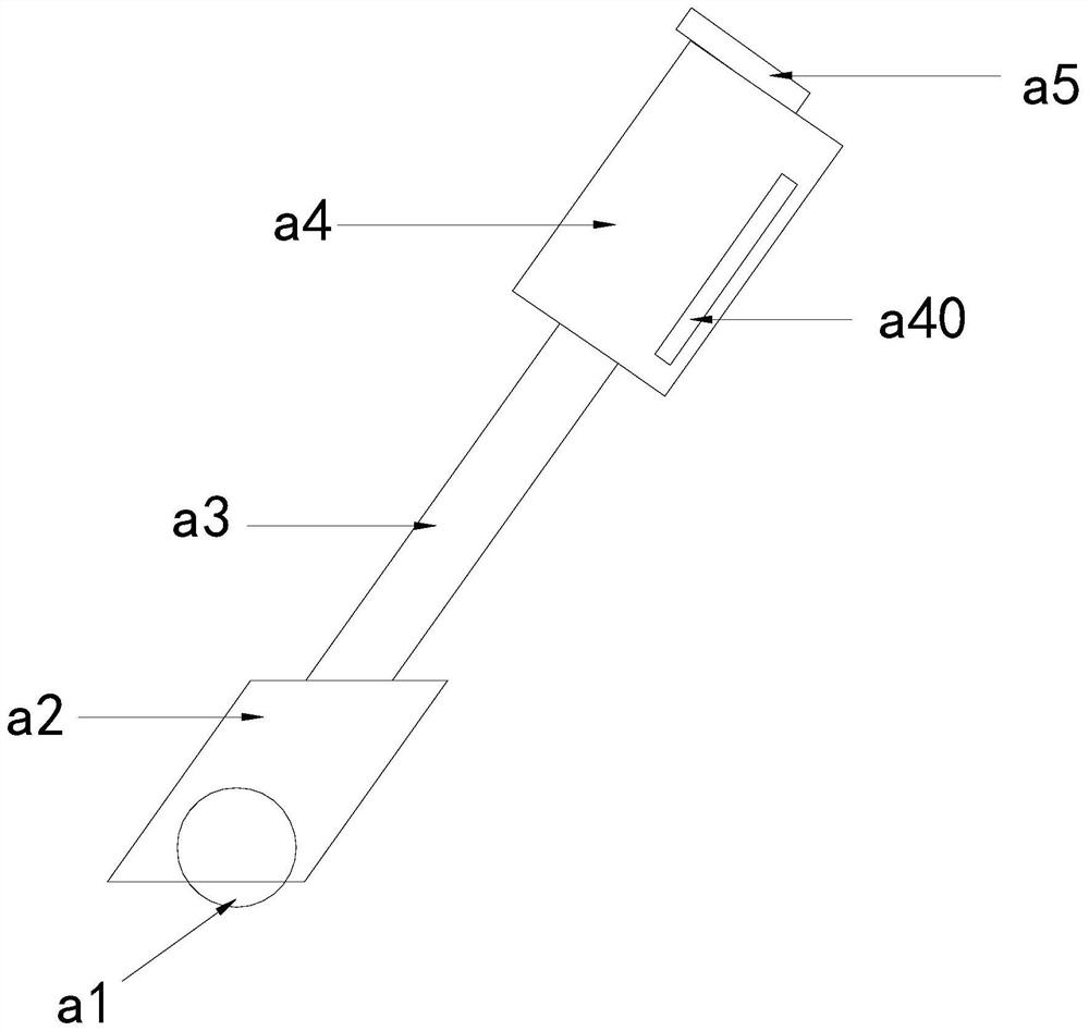
The invention discloses a floor polisher, the structure of which comprises a dust suction cover, a reminder device, a machine base, a motor, a fan, a handrail, a first air duct, a dust collecting box, a moving wheel, a second air duct, and a machine base One end of the bottom is connected with a dust cover, and there is a grinding block inside the dust cover, and a moving wheel is installed at the other end of the machine base, and the handrail is set above the moving wheel and connected with the machine base. The motor is connected to the grinding block, the dust collection box is connected to the dust collection hood through the second air duct, the fan is connected to the top of the dust collection box and communicates with the dust collection box through the first air duct, and a reminder device is installed outside the dust collection hood , the reminder device includes an alarm, a fixed cover, and a movable structure. The beneficial effects of the present invention are: through the surrounding design, the alarm can be activated when a hard object in any direction touches the arc-shaped plate, and the staff can be immediately reminded , to avoid damage caused by contact between the grinding block and hard objects.
Description
technical field [0001] The invention relates to the construction field, in particular to a floor polisher. Background technique [0002] The floor polisher, also known as the terrazzo machine, is a construction machine equipped with a rotating disc to polish the terrazzo floor. It is a mechanical equipment used for pulping, smoothing, and troweling on the surface of cement concrete. [0003] When the existing floor polisher is working, since the ground may protrude with steel pipes or hard debris, if you do not pay attention when the floor polisher is moving, it is easy to make the module contact with it for hard friction, causing damage to the grinding block. damage. Contents of the invention [0004] The main purpose of the present invention is to overcome the deficiencies of the prior art and provide a floor polisher. [0005] The present invention adopts the following technical solutions to achieve: a floor polisher, its structure includes a dust suction cover, a rem...
Claims
Application Information
Patent Timeline
Application Date:The date an application was filed.
Publication Date:The date a patent or application was officially published.
First Publication Date:The earliest publication date of a patent with the same application number.
Issue Date:Publication date of the patent grant document.
PCT Entry Date:The Entry date of PCT National Phase.
Estimated Expiry Date:The statutory expiry date of a patent right according to the Patent Law, and it is the longest term of protection that the patent right can achieve without the termination of the patent right due to other reasons(Term extension factor has been taken into account ).
Invalid Date:Actual expiry date is based on effective date or publication date of legal transaction data of invalid patent.

