Special inspection robot for electric power distribution cabinet

A technology for inspection robots and power distribution cabinets, applied in the direction of manipulators, electrical components, switchgear, etc., can solve problems such as collisions, failures of electronic devices and control modules, and impact on inspection work, and achieve easy disassembly and assembly Effect

Inactive Publication Date: 2020-12-01
GUANGDONG POWER GRID CORP ZHAOQING POWER SUPPLY BUREAU
View PDF9 Cites 1 Cited by
  • Summary
  • Abstract
  • Description
  • Claims
  • Application Information

AI Technical Summary

Problems solved by technology

[0002] When the electronic devices inside the power distribution cabinet fail, the power distribution cabinet needs to be overhauled. In order to prevent safety accidents during manual inspection, inspections are often carried out by special inspection robots for power distribution cabinets. For example, the public number is CN111409720A, a Chinese patent with a publication date of 2020.07.14 - a power distribution inspection robot, which replaces manual inspections, and uses the detection mechanism on the mechanical arm to detect power distribution equipment, and has a walking function at the same time and upgrade functions to realize unmanned inspection and improve the safety of inspection, but the inspection robot disclosed in this patent has the following disadvantages: when the inspection robot inspects the power distribution cabinet, it needs to move, and due to the The environment of the electric cabinet makes it easy for the inspection robot to collide during the movement, and the inspection robot is equipped with a control unit to control the movement and maintenance of the inspection robot through the control unit. When the inspection robot collides It is easy to cause failures of electronic devices and control modules in the control unit, affecting the continuation of inspection work and inefficiency

Method used


Image

  • Special inspection robot for electric power distribution cabinet
  • Special inspection robot for electric power distribution cabinet
  • Special inspection robot for electric power distribution cabinet

Examples


Embodiment 1

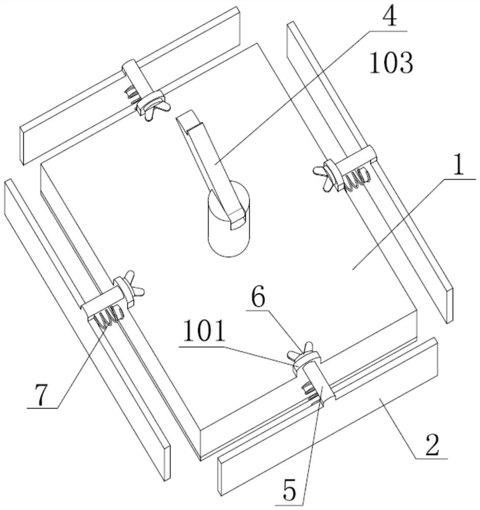
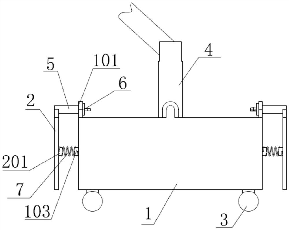
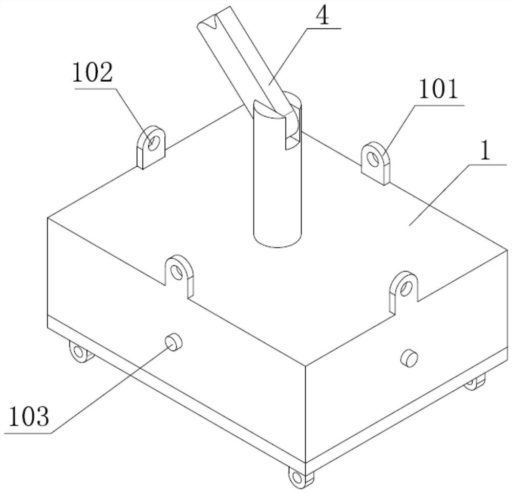
[0027] Such as Figure 1-Figure 4 As shown, a special inspection robot for power distribution cabinets, including a main control box 1, the four sides of the main control box 1 are connected with anti-collision plates 2, and the four corners of the bottom of the main control box 1 are all rotated Connected with a moving wheel 3, the moving wheel 3 is a moving steering wheel controlled by a motor. The top of the main control box 1 is provided with a mechanical arm 4. The mechanical arm 4 adopts a six-degree-of-freedom mechanical arm. The equipment for testing in the electric cabinet, such as infrared cameras, multimeters, etc., is fixed with connecting plates 101 on the four sides of the main control box 1, and the connecting plates are provided with sliding holes 102, and the top of the anti-collision plate 2 is fixedly connected with sliding holes. The sliding rod 5 adapted to the hole 102, the insertion end of the sliding rod 5 passes through the sliding hole 102, the insert...


PUM


Abstract

The invention discloses a special inspection robot for an electric power distribution cabinet. The special inspection robot comprises a main control box, four side surfaces of the main control box areconnected with anti-collision plates, moving wheels are arranged at the bottom of the main control box, a mechanical arm is arranged at the top of the main control box, detection equipment is mountedat the tail end of the mechanical arm, connecting plates are fixed on the four side edges of the main control box, sliding holes are formed in the connecting plate, the tops of the anti-collision plates are fixedly connected with sliding rods matched with the sliding holes, the inserting ends of the sliding rods penetrate through the sliding holes, threaded holes are formed in the inserting endsof the sliding rods, limiting pieces are in threaded connection with the interiors of the threaded holes and used for limiting, first mounting protruding blocks are fixed to the four side faces of themain control box, second mounting protruding blocks are fixed to the faces, close to the sliding rods, of the anti-collision plates, and telescopic springs are fixedly connected between the first mounting protruding blocks and the second mounting protruding blocks. The inspection robot has the function of performing anti-collision protection on the main control box, collision of the inspection robot in the moving process is avoided, and the efficiency of inspection work is improved.

Description

technical field [0001] The invention relates to the technical field of electric power inspection, in particular to a special inspection robot for electric power distribution cabinets. Background technique [0002] When the electronic devices inside the power distribution cabinet fail, the power distribution cabinet needs to be overhauled. In order to prevent safety accidents during manual inspection, inspections are often carried out by special inspection robots for power distribution cabinets. For example, the public number is CN111409720A, a Chinese patent with a publication date of 2020.07.14 - a power distribution inspection robot, which replaces manual inspections, and uses the detection mechanism on the mechanical arm to detect power distribution equipment, and has a walking function at the same time and upgrade functions to realize unmanned inspection and improve the safety of inspection, but the inspection robot disclosed in this patent has the following disadvantage...

Claims


Application Information

Patent Timeline
Patent Type & Authority Applications(China)
IPC IPC(8): B25J19/06H02B3/00
CPCB25J19/06H02B3/00
Inventor 胡宇轩杨喆曾彦超谢家力冯进杰巫志安李俊宏
Owner GUANGDONG POWER GRID CORP ZHAOQING POWER SUPPLY BUREAU
Why Eureka
Try Eureka