Automatic box falling device and operation method thereof

A box-dropping and automatic technology, applied in packaging and other directions, can solve problems such as a large amount of manpower, low work efficiency, and insufficient hygiene guarantee

Pending Publication Date: 2020-12-01
燕诚智能设备制造河北有限公司
View PDF6 Cites 0 Cited by
  • Summary
  • Abstract
  • Description
  • Claims
  • Application Information

AI Technical Summary

Problems solved by technology

[0003] At present, in the production process of large-scale boxed lunches in China, especially the process of placing the lunch box under the rice distribution mechanism is mainly carried out manually. When packing the box, the staff needs to manually place the lunch box under the rice distribution mechanism to undertake Rice, but this way of manuall

Method used


Image

  • Automatic box falling device and operation method thereof
  • Automatic box falling device and operation method thereof
  • Automatic box falling device and operation method thereof

Examples


Embodiment 1

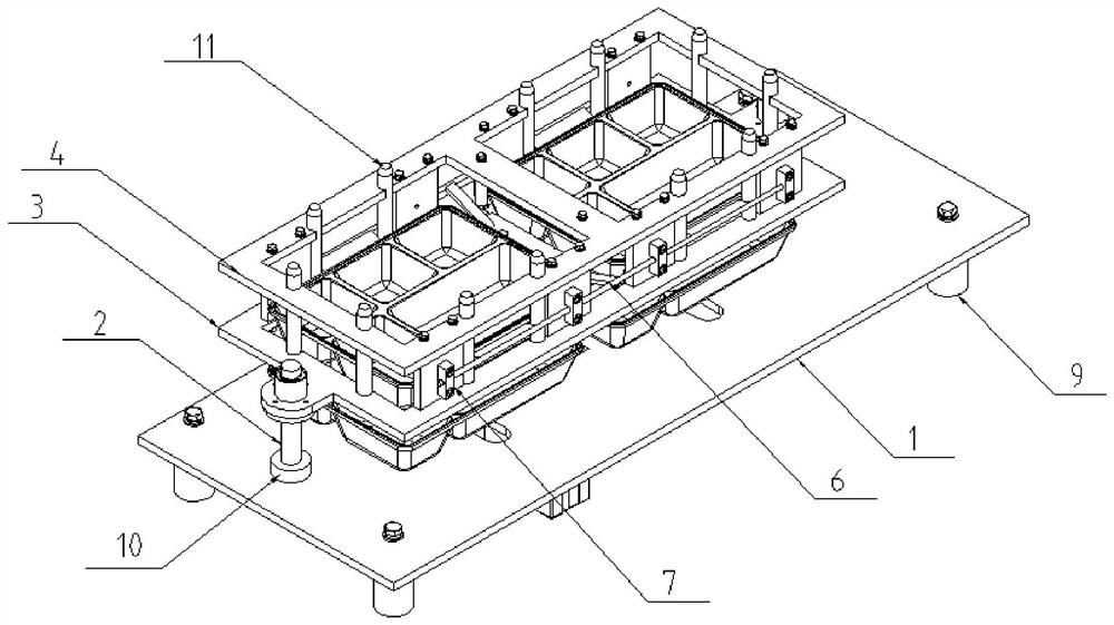
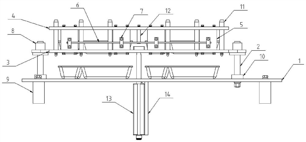
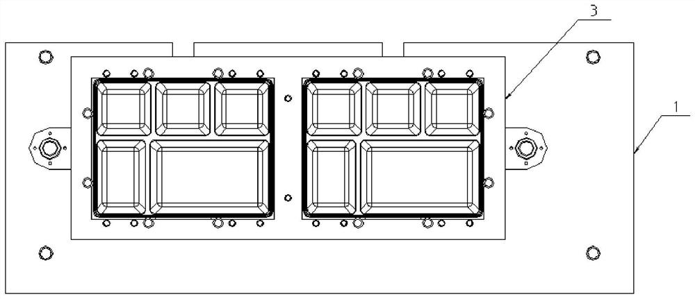
[0032] Please refer to figure 1 , figure 2 , image 3 and Figure 4 The schematic structural view of the first embodiment of an automatic box dropping device provided by the present application is shown, including: a bottom plate 1 arranged horizontally and a guide assembly arranged on the bottom plate 1;

[0033] The guide assembly includes: a first guide plate 3 and a second guide plate 4 arranged in parallel; the first guide plate 3 and the second guide plate 4 are correspondingly provided with at least two lunch box accommodating parts; Both sides of the lead-in plate 3 are affixed to the base plate 1 through the guide post 2 respectively; the top of the guide post 2 is provided with a linear bearing 8; the second guide plate 4 is located above the first lead-in plate 3, And it is affixed to the first lead-in plate 3 through the support blocks 5 evenly arranged; the second lead-in plate 4 is affixed with two symmetrically arranged lead-in swing shafts 6; the lead-in sw...

Embodiment 2

[0059] An operation method of an automatic box drop device, based on the above-mentioned automatic box drop device, comprising:

[0060] Step S1, the operator first puts the stacked lunch boxes into the lunch box accommodating part of the device;

[0061] Step S2, start the cylinder, its piston rod moves upwards, and drives the push block to move upward until the push block pushes the fixed end of the lead-in pendulum shaft, and the lead-in pendulum shaft moves, so that the lunch box at the bottom falls on the bottom plate, and the rest of the lunch boxes are lifted up ;

[0062] Step S3, the piston rod of the cylinder continues to extend to its maximum extension distance, so that the bottom of the remaining lunch boxes is higher than the top of the lunch boxes on the bottom plate, and the lunch boxes on the bottom plate are pushed away by the slider;

[0063] Step S4, the piston rod of the cylinder shrinks, so that a lunch box at the bottom of the lunch box accommodating par...


PUM


Abstract

The invention discloses an automatic box falling device and an operation method thereof. The automatic box falling device comprises a horizontally-arranged bottom plate and a guide assembly arranged on the bottom plate. The bottom plate is used as a basic mounting piece of the device for mounting the guide assembly. An operator puts stacked lunch boxes into a lunch box accommodating part of the device, and a driving assembly moves upwards to drive the guide assembly to move upwards, so that the lunch boxes fall on the bottom plate, the driving assembly continues to drive the guide assembly tomove upwards, the bottom lunch boxes fall on the bottom plate, and the other lunch boxes are supported. When the driving assembly extends to the maximum extending distance, the bottoms of the other lunch boxes are higher than the top of the lunch box on the bottom plate, and then the lunch boxes on the bottom plate are pushed away through a sliding block; then the driving assembly is contracted, so that one lunch box at the bottom of the lunch box accommodating part falls onto the bottom plate; and when the driving assembly extends to the maximum extending distance, the bottoms of other lunchboxes are higher than the top of the lunch box on the bottom plate. Therefore, the purposes of enabling automatic box falling and reducing the labor intensity of workers are achieved.

Description

technical field [0001] The present disclosure generally relates to the technical field of central kitchen equipment, and in particular relates to an automatic box dropping device and an operation method thereof. Background technique [0002] As a popular staple food, rice has a huge market demand. With the rapid development of the fast food industry, the supply of box lunches is increasing day by day in the catering industries such as corporate employee meals, student nutritious meals, airline catering, and railway catering. [0003] At present, in the production process of large-scale boxed lunches in China, especially the process of placing the lunch box under the rice distribution mechanism is mainly carried out manually. When packing the box, the staff needs to manually place the lunch box under the rice distribution mechanism to undertake Rice, but this way of manually placing lunch boxes not only requires a lot of manpower, but also has high labor intensity, low work ...

Claims


Application Information

Patent Timeline
IPC IPC(8): B65B43/42B65B43/48
CPCB65B43/42B65B43/48
Inventor 赵荣艳
Owner 燕诚智能设备制造河北有限公司
Why Eureka
Try Eureka