Electromechanical equipment mounting device and using method thereof

A technology of electromechanical equipment and installation device, which is applied in the direction of lifting equipment braking device, hoisting device, transportation and packaging, etc., to achieve the effect of improving safety performance and increasing fixing effect

Active Publication Date: 2020-12-01
广东爱科建设工程有限公司
View PDF13 Cites 1 Cited by
  • Summary
  • Abstract
  • Description
  • Claims
  • Application Information

AI Technical Summary

Problems solved by technology

The invention has simple structure and reasonable design, and can quickly and safely install electromechanical equipment in place, which is beneficial to popularizat

Method used


Image

  • Electromechanical equipment mounting device and using method thereof
  • Electromechanical equipment mounting device and using method thereof
  • Electromechanical equipment mounting device and using method thereof

Examples


Embodiment 1

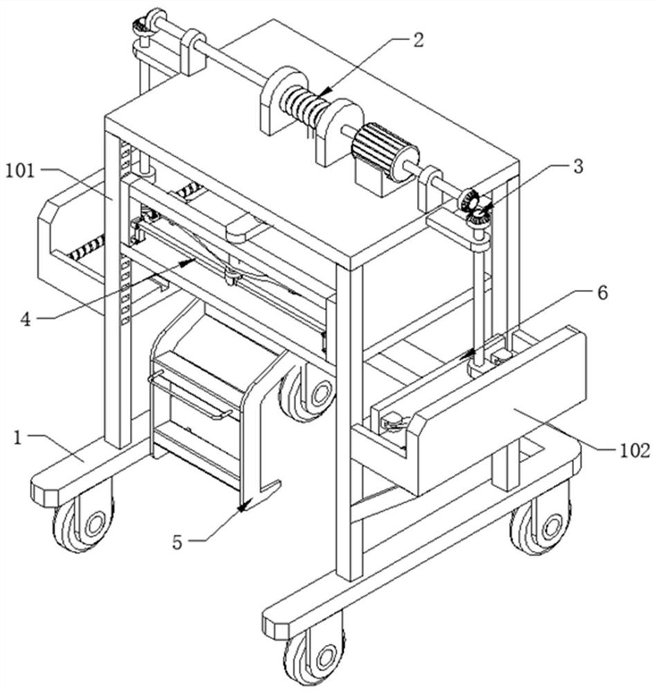
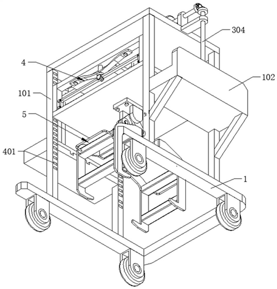
[0038] refer to Figure 1-7 , an electromechanical equipment installation device, including a U-shaped horizontal frame 1 and a first support frame 101, the first support frame 101 is connected to the top wall of the U-shaped horizontal frame 1, and a drive motor 201 is connected to the top wall of the first support frame 101 , the output end of the drive motor 201 is respectively connected to the lifting assembly 2 and the transmission assembly 3, the output end of the lifting assembly 2 passes through and is connected to the anti-fall assembly 4, the anti-fall assembly 4 is slidably connected to the inner wall of the first support frame 101, and the first The inner wall of the support frame 101 is dug with a card slot 401 matching the anti-fall assembly 4, the bottom wall of the anti-fall assembly 4 is connected with the first clamping assembly 5, and the transmission assembly 3 is connected to the side wall of the first support frame 101 through a fixing block. , and the en...

Embodiment 2

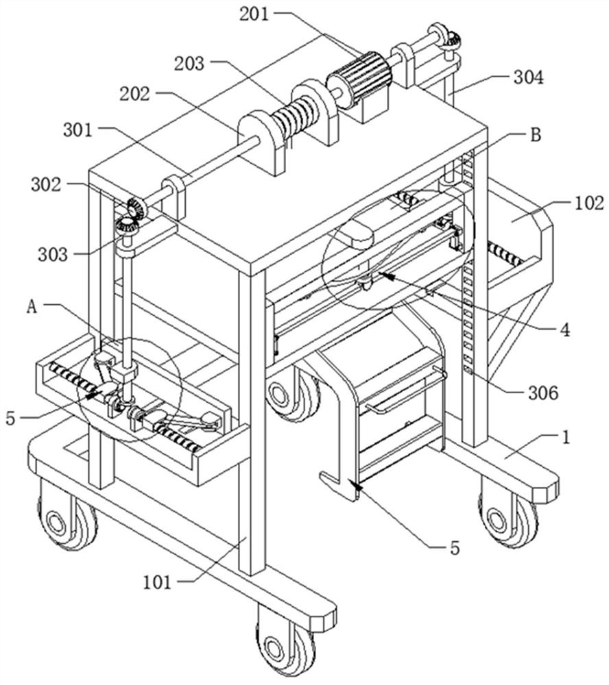
[0046] refer to Figure 1-5 , an electromechanical equipment installation device, which is basically the same as Embodiment 1, furthermore, the transmission assembly 3 includes a first rotating shaft 301, the first rotating shaft 301 is connected to the output end of the driving motor 201, and the first rotating shaft 301 is far away from the driving One end of the output end of the motor 201 is connected with a first bevel gear 302, the first bevel gear 302 is meshed with a second bevel gear 303, the second bevel gear 303 is connected with a second rotating shaft 304 on the bottom wall, and the second rotating shaft 304 bottom wall A third bevel gear 305 is connected to it, and a fourth bevel gear 306 is meshed with the third bevel gear 305 , and the fourth bevel gear 306 is connected with the second clamping assembly 6 .

[0047] The second clamping assembly 6 includes a threaded mandrel 602, one end of the threaded mandrel 602 is connected to the outer wall of the fourth be...

Embodiment 3

[0052] refer to Figure 1-7 , an electromechanical equipment installation device, which is basically the same as that of Embodiment 1, furthermore, the first clamping assembly 5 includes a second connection seat 501, and the second connection seat 501 is connected to the bottom wall of the fall prevention assembly 4, and the second A connecting rod assembly is rotatably connected to the inner wall of the connecting seat 501 , and the end of the connecting rod assembly away from the second connecting seat 501 is connected with a clamping claw 502 .

[0053] The connecting rod assembly includes a first connecting rod 503, a second connecting rod 504, a third connecting rod 505 and a fourth connecting rod 506, and the first connecting rod 503 and the second connecting rod 504 are rotatably connected to the second connecting rod through a first pivot pin. On the inner wall of the second connecting seat 501, and the first connecting rod 503 and the second connecting rod 504 are con...


PUM


Abstract

The invention discloses an electromechanical equipment mounting device and a using method thereof, and belongs to the technical field of electromechanical equipment mounting auxiliary devices. The electromechanical equipment mounting device comprises a U-shaped transverse frame and a first supporting frame; the first supporting frame is connected to the top wall of the U-shaped transverse frame; the top wall of the first supporting frame is connected with a driving motor; the output end of the drive motor is connected with a lifting assembly and a transmission assembly; the output end of the lifting assembly penetrates through and is connected with an anti-falling assembly; a clamping groove matched with the anti-falling assembly is formed in the inner wall of the first supporting frame; afirst clamping assembly is connected with the bottom wall of the anti-falling assembly; a second clamping assembly is connected with the end, away from the lifting assembly, of a transmission assembly; and the second clamping assembly is connected with the outer wall of the first supporting frame through a second supporting frame. According to the device, electromechanical equipment can be stablyclamped, the situation that damage and potential safety hazards are caused due to falling in the installation process is effectively avoided, and therefore the safety performance of the device is effectively improved.

Description

technical field [0001] The invention relates to the technical field of mechanical and electrical equipment installation auxiliary devices, in particular to a mechanical and electrical equipment installation device and a use method thereof. Background technique [0002] Electromechanical equipment generally refers to machinery, electrical appliances and electrical automation equipment, which are widely used in the construction field. During the placement and installation of electromechanical equipment, installation devices are often required to facilitate the use of electromechanical equipment. [0003] After retrieval, the invention patent with the publication number CN109437023A discloses a gantry framework for the installation of electromechanical equipment. The gantry framework for the installation of electromechanical equipment includes a first motor, a second motor, a slider, a timing belt, and a beam , pulleys, chutes, support columns, bases, hooks, controllers, buckle...

Claims


Application Information

Patent Timeline
IPC IPC(8): B66C5/02B66C1/42B66C13/00
CPCB66C5/02B66C1/42B66C13/00
Inventor 魏海虎
Owner 广东爱科建设工程有限公司
Why Eureka
Try Eureka