A heat treatment furnace for drive shafts
A heat treatment furnace and drive shaft technology, applied in heat treatment furnaces, heat treatment equipment, heat treatment process control, etc., can solve problems such as wasting energy, increasing costs, switching without functions, etc., to reduce production costs, uniform heat treatment, and save energy Effect
Active Publication Date: 2021-11-26
CHONGQING CHANGJIANG INDAL FURNACE MFG
View PDF0 Cites 0 Cited by
- Summary
- Abstract
- Description
- Claims
- Application Information
AI Technical Summary
Problems solved by technology
The heat treatment furnace is an industrial furnace for heat treatment of parts. The existing heat treatment furnaces for heat treatment of transmission shafts have the following disadvantages: 1. The opening and closing of the heat treatment furnace, the turning of the workpiece to be processed and the temperature sensor are respectively driven by multiple power sources. The reciprocating movement increases the cost and wastes energy; 2. During the heat treatment process, the realized function mode is relatively fixed, without function switching, and it is not convenient to control the quality of heat-treated parts
Method used
View moreImage
Smart ImageViewing Examples
Examples
Embodiment Construction
[0042] The present invention will be further described below in conjunction with drawings and embodiments.
Login to View More PUM
 Abstract
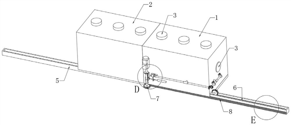
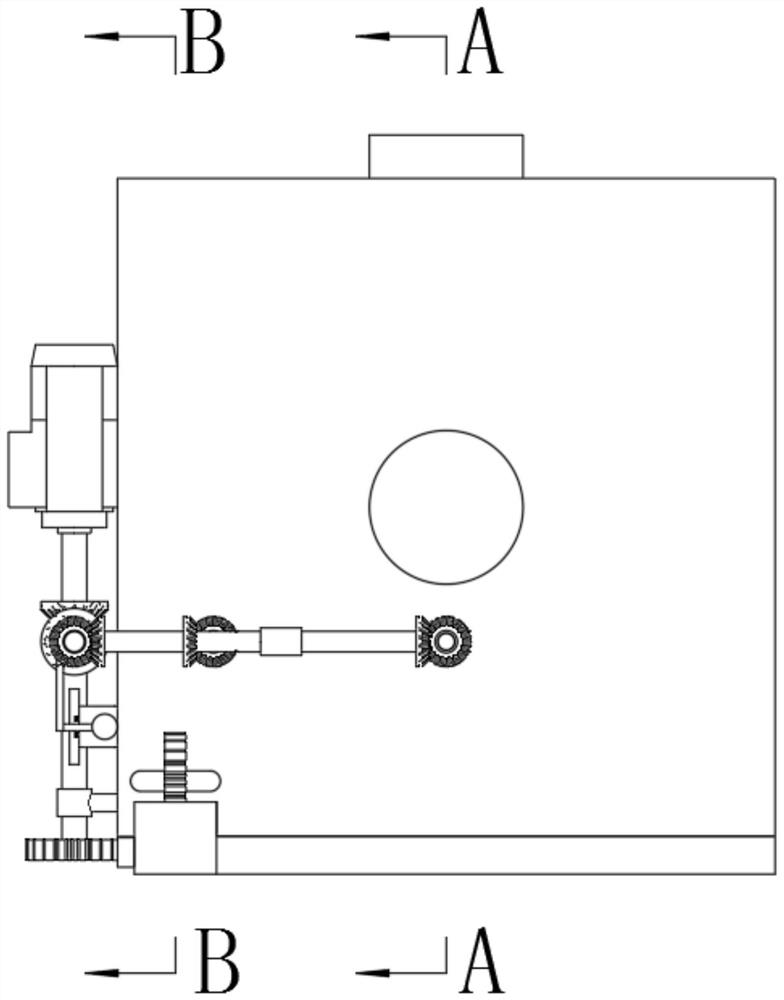
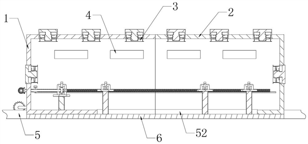
The invention relates to a heat treatment furnace for transmission shafts, comprising two relatively moving first heat treatment furnaces and second heat treatment furnaces, a heating unit, a temperature measuring unit, a turning unit for placing and turning parts to be treated, and a power unit ; the heating unit is fixed on the first heat treatment furnace and the second heat treatment furnace, the temperature measurement unit and the turning unit are arranged in the space formed by the first heat treatment furnace and the second heat treatment furnace, and the power unit passes the same power The source can selectively drive the relative movement of the first heat treatment furnace and the second heat treatment furnace and the remote movement of the turning unit; the temperature measuring unit is electrically connected with the heating unit. The invention drives the relative movement of the first heat treatment furnace and the second heat treatment furnace through the motor to realize the opening and closing of the airtight cavity, uses the heating unit to heat, and drives the workpiece to be processed to flip and the temperature measurement unit to reciprocate through the same motor to realize the heat treatment of the parts .
Description
technical field [0001] The invention relates to the field of heat treatment equipment, in particular to a heat treatment furnace for transmission shafts. Background technique [0002] In the production process of the transmission shaft, the quenching of the transmission shaft is realized by placing the parts to be processed in a chamber, then raising the temperature in the chamber to the specified temperature, keeping the temperature for a period of time, and then taking out the parts to cool quickly. Improve drive shaft performance. The heat treatment furnace is an industrial furnace for heat treatment of parts. The existing heat treatment furnaces for heat treatment of transmission shafts have the following disadvantages: 1. The opening and closing of the heat treatment furnace, the turning of the workpiece to be processed and the temperature sensor are respectively driven by multiple power sources. 2. During the heat treatment process, the mode of the realized function i...
Claims
Login to View More Application Information
Patent Timeline
 Patent Type & Authority Patents(China)
IPC IPC(8): C21D9/28C21D11/00
CPCC21D9/0006C21D9/0025C21D9/28C21D11/00
Inventor 蒋波谢洪砖杨天虹谯中昂伍元祥
Owner CHONGQING CHANGJIANG INDAL FURNACE MFG
Features
- R&D
- Intellectual Property
- Life Sciences
- Materials
- Tech Scout
- Unparalleled Data Quality
- Higher Quality Content
- 60% Fewer Hallucinations
Learn More Browse by: Latest US Patents, China's latest patents, Technical Efficacy Thesaurus, Application Domain, Technology Topic, Popular Technical Reports.
© 2025 PatSnap. All rights reserved.Legal|Privacy policy|Modern Slavery Act Transparency Statement|Sitemap|About US| Contact US: help@patsnap.com


