Quenching treatment equipment and quenching treatment process for engine crankshaft

A technology for processing equipment and engines, applied to heat treatment equipment, quenching devices, heat treatment furnaces, etc., can solve problems such as difficult clamping operations, difficult uniform cooling, and large cross-sectional size of sampling parts, so as to improve work efficiency, stable and uniform cooling, The effect of reducing work intensity

Active Publication Date: 2020-12-01
天津爱信热处理有限公司
View PDF7 Cites 4 Cited by
  • Summary
  • Abstract
  • Description
  • Claims
  • Application Information

AI Technical Summary

Problems solved by technology

[0003] Due to the complex shape of the engine crankshaft and the large cross-sectional size of the sampling part, it is difficult to perform uniform cooling during the coolant cooling process, and the requirements for the comprehensive mechanical properties of the cooling device are relatively high. However, the engine crankshaft quenching treatment currently on the market has the following problems during operation Problem: a. During the cooling process of the engine crankshaft, it is difficult to ensure that the surface of the engine crankshaft with complex shape is uniformly cooled in the coolant. The different cooling time of each part of the engine crankshaft may cause excessive cracking tendency of the crankshaft, resulting in a high scrap rate High, b. In the traditional engine crankshaft quenching process, due to the complex shape of the engine crankshaft, it is difficult to provide a stable clamping operation for it, and it is impossible to provide a certain degree of rotation for the engine crankshaft during the cooling process to stabilize the engine crankshaft The effect of rapid cooling;

Method used


Image

  • Quenching treatment equipment and quenching treatment process for engine crankshaft
  • Quenching treatment equipment and quenching treatment process for engine crankshaft
  • Quenching treatment equipment and quenching treatment process for engine crankshaft

Examples


Embodiment Construction

[0025] In order to make the technical means realized by the present invention, creative features, goals and effects easy to understand, the following combination Figure 1 to Figure 7 , to further elaborate the present invention.

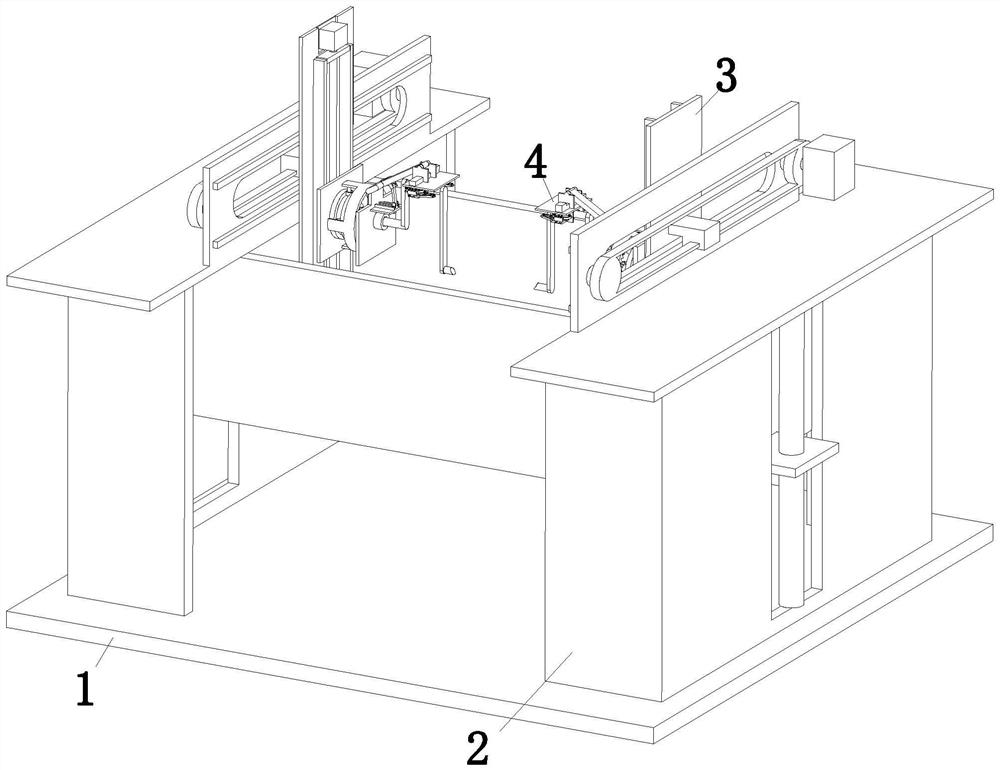
[0026] An engine crankshaft quenching treatment equipment, comprising a mounting base plate 1, a support frame 2, a cooling mechanism 3 and a clamping and rotating mechanism 4, the upper end of the mounting base plate 1 is symmetrically installed with a support frame 2, and the support frame 2 is symmetrically installed by sliding fit There is a cooling mechanism 3 on which a clamping and rotating mechanism 4 is mounted symmetrically through rotational fit, and the clamping and rotating mechanism 4 is located between the support frames 2 .

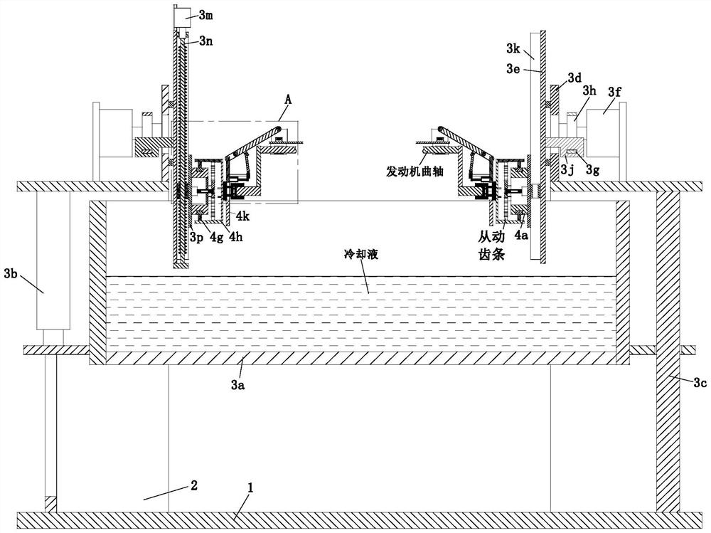
[0027]The cooling mechanism 3 includes a cooling box 3a, a lifting electric push rod 3b, a lifting slide bar 3c, a shifting bottom plate 3d, a shifting slide plate 3e, a shifting motor 3f, a synchronous belt 3g,...


PUM


Abstract

The invention provides quenching treatment equipment and a quenching treatment process for an engine crankshaft. The equipment comprises a mounting bottom plate, supporting frames, cooling mechanismsand clamping rotating mechanisms, the supporting frames are symmetrically mounted at the upper end of the mounting bottom plate, the cooling mechanisms are symmetrically mounted on the supporting frames in a sliding fit mode, the clamping rotating mechanisms are symmetrically mounted on the cooling mechanisms in a rotating fit mode, and the clamping rotating mechanisms are located between the supporting frames. The relative position of the crankshaft in the cooling process is adjusted in real time through a shifting motor and a lifting motor; the working intensity of workers is reduced; the clamping rotating mechanisms are capable of stably clamping the engine crankshaft in a complex shape; the crankshaft is continuously rotated in the cooling process to enable the complex surface of the crankshaft to be stably, evenly and rapidly cooled; and the working efficiency of cooling work is improved.

Description

technical field [0001] The invention relates to the technical field of engine crankshaft quenching treatment, in particular to engine crankshaft quenching treatment equipment and a quenching treatment process. Background technique [0002] The engine crankshaft is generally made of special 42CrMoA steel. After being forged and formed and kept warm for a period of time, it needs to be taken out of the furnace and cooled by cooling liquid or sprayed with water, sprayed or blown for metal heat treatment. [0003] Due to the complex shape of the engine crankshaft and the large cross-sectional size of the sampling part, it is difficult to perform uniform cooling during the coolant cooling process, and the requirements for the comprehensive mechanical properties of the cooling device are relatively high. However, the engine crankshaft quenching treatment in the current market has the following problems during operation Problem: a. During the cooling process of the engine crankshaf...

Claims


Application Information

Patent Timeline
Patent Type & Authority Applications(China)
IPC IPC(8): C21D9/30C21D1/63
CPCC21D1/63C21D9/0062C21D9/30
Inventor 郭庆利周洋
Owner 天津爱信热处理有限公司
Why Eureka
Try Eureka