
Diagnosis system based on multipath acquisition of gearbox operation vibration data

A vibration data and diagnostic system technology, applied in the field of diagnostic systems, can solve problems such as excessive signal, large impact signal, and inability to monitor the gearbox, and achieve the effect of improving measurement accuracy

Inactive Publication Date: 2020-12-01
常州源数菁英软件技术有限公司
View PDF9 Cites 0 Cited by
  • Summary
  • Abstract
  • Description
  • Claims
  • Application Information

AI Technical Summary

Problems solved by technology

[0003] At present, in conventional gearbox vibration monitoring, there is usually only one vibration sensor, which can only be used to monitor the normal operating vibration state of the gear. Since the signal is relatively small during normal operation, a larger magnification factor is used to ensure the signal conditioning. The acquisition of small signals is accurate, but due to the influence of the working environment of the gear itself, there will often be a large impact signal. At this time, the excessive amplification and conditioning circuit will easily cause the signal to be too large and affect the subsequent analog-to-digital conversion, causing the analog-to-digital conversion to overflow. Unable to accurately monitor the gearbox

Method used


Image

  • Diagnosis system based on multipath acquisition of gearbox operation vibration data
  • Diagnosis system based on multipath acquisition of gearbox operation vibration data
  • Diagnosis system based on multipath acquisition of gearbox operation vibration data

Examples


Embodiment Construction

[0031] The present invention will be further described below. The following examples are only used to illustrate the technical solution of the present invention more clearly, but not to limit the protection scope of the present invention.

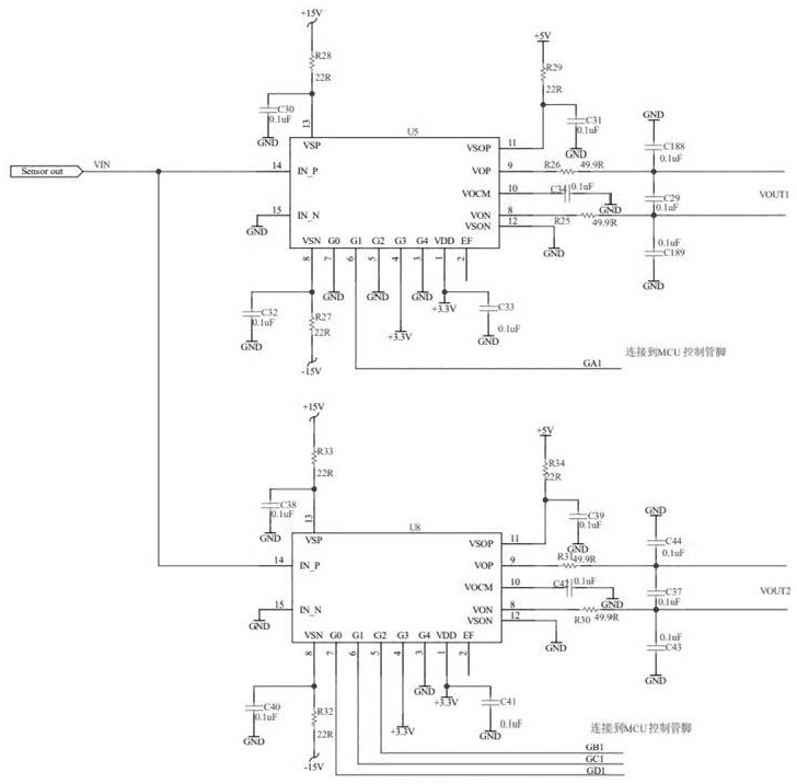
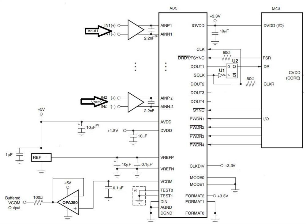
[0032] The invention provides a diagnosis system based on multi-channel acquisition of vibration data of a gearbox, including: a sensor excitation output circuit, a double amplifier circuit, a synchronous analog-to-digital conversion circuit and a diagnosis module;

[0033] specific,

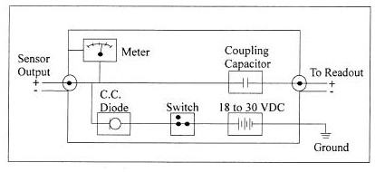
[0034] The sensor excites the output circuit for outputting the vibration signal of the gearbox.

[0035] The dual amplifier circuit is used to generate two amplified signals from the vibration signal of the gearbox.

[0036] The synchronous analog-to-digital conversion circuit is used to convert the two amplified signals into digital signals.

[0037] The diagnosis module is used to select effective digital signals according to the output of the synchrono...


PUM


Abstract

The invention discloses a diagnosis system based on multipath acquisition of gearbox operation vibration data. The diagnosis system comprises a sensor excitation output circuit, a double-amplificationcircuit, a synchronous analog-to-digital conversion circuit and a diagnosis module, wherein the sensor excitation output circuit is used for outputting a gearbox vibration signal; the double-amplification circuit is used for amplifying the gearbox vibration signal to generate two paths of amplified signals; the synchronous analog-to-digital conversion circuit is used for converting the two pathsof amplified signals into digital signals; and the diagnosis module is used for outputting and selecting the valid digital signal to monitor a gearbox operation vibration state. According to the diagnosis system, the double amplification circuits are arranged, the small gearbox operation vibration signal is amplified by a certain multiple to meet the input requirement of the analog-to-digital converter, meanwhile, the signal gearbox operation impact large can be reduced by a certain multiple to meet the input requirement of the analog-to-digital converter, the measurement precision of the signal within the full output range is improved, and the abnormity of the monitoring signal can be found in time.

Description

technical field [0001] The invention relates to a diagnosis system based on multi-channel acquisition of vibration data of a gearbox, and belongs to the technical field of mechanical equipment monitoring. Background technique [0002] With the development of modern industry, mechanical equipment is developing towards large-scale, continuous, precise and automatic, which makes the structure of equipment more and more complex, and the requirements for performance indicators are also getting higher and higher. Therefore, higher requirements are placed on the reliability of mechanical equipment (such as equipment with complex working conditions such as high-speed rail gearboxes). Whether the equipment can operate safely and reliably is very important for ensuring product quality, improving production capacity, and ensuring safety. Usually, major equipment operates in a complex working environment, coupled with its own complex structure, which increases the difficulty of conditio...

Claims


Application Information

Patent Timeline
IPC IPC(8): G01M13/021G01M13/028G01H17/00
CPCG01H17/00G01M13/021G01M13/028
Inventor 蒋一松徐海涛黄欢杨刚
Owner 常州源数菁英软件技术有限公司
Learn More