Rotating shaft angle and speed measuring device

A speed measurement and angle technology, applied in the field of rotating shaft motion parameter measurement equipment, can solve problems such as inability to output correct rotational speed and angle signals, inability to meet sine/cosine signal interpolation, uneven chip induction sensitivity, etc., to achieve measurement accuracy and sensitivity. The effect of improving, stable and balanced work performance, and improving detection sensitivity

Active Publication Date: 2018-09-21
北京玻迅基业科技有限公司
View PDF6 Cites 0 Cited by
  • Summary
  • Abstract
  • Description
  • Claims
  • Application Information

AI Technical Summary

Problems solved by technology

Due to the slight difference in the installation position of the permanent magnet in the rotating shaft angle and speed measuring device based on the above structure in the prior art, the sensing sensitivity of the chip integrated with multiple magnetoresistive sensors after assembly is uneven, and some products even There is a technical problem of low detection accuracy
[0004] In addition, since the output signal strength of the magnetoresistive sensor in the magnetic rotary encoder will weaken as the input rotation speed increases, when the input speed increases to a certain value (such as 20000r / min), the signal weakens to the point that it cannot satisfy the sine / cosine signal interpolation , Self-calibration driver (hereinafter referred to as the driver) input signal strength requirements
In order to increase the signal strength, the method of increasing the power supply voltage of the magnetoresistive sensor is adopted. When the gear to be tested is rotating or stationary, it will cause figure 1 The values ​​of the offset voltages V1 and V2 of the two outputs of each bridge (such as the sinusoidal positive (SIN+) and sinusoidal negative (SIN-) of the sinusoidal output) exceed the allowable input range of the driver, resulting in the failure of the entire system to output the correct Speed ​​and angle signals, cosine (COS+ and COS-) output and zero output (ZERO+ and ZERO-) are similar

Method used


Image

  • Rotating shaft angle and speed measuring device
  • Rotating shaft angle and speed measuring device
  • Rotating shaft angle and speed measuring device

Examples


Embodiment 1

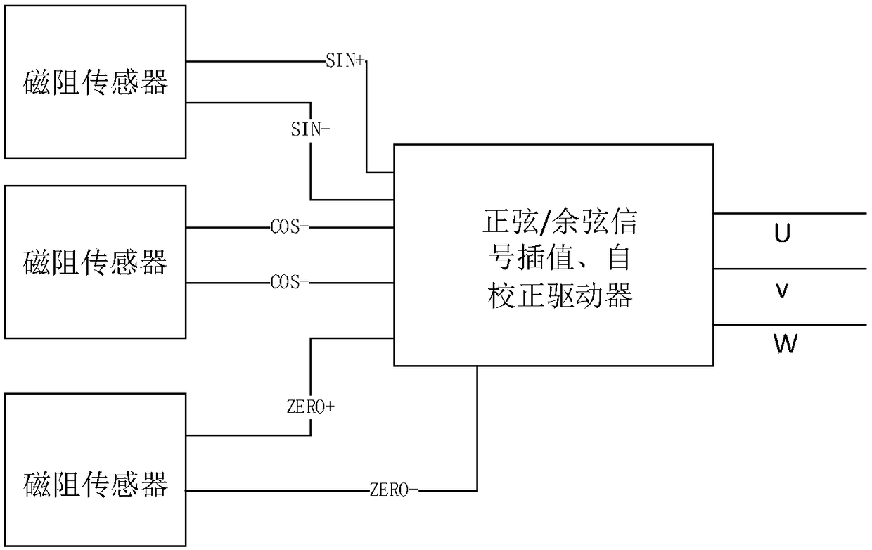
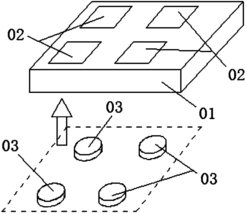
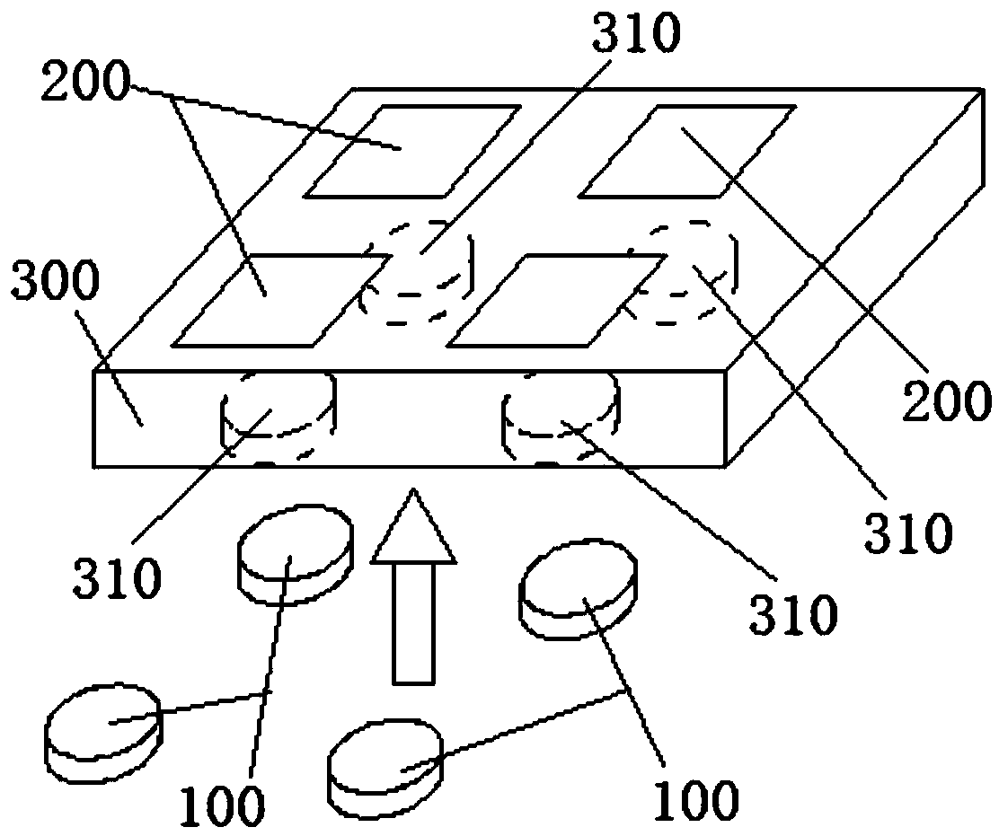
[0038] image 3 As shown, the present invention provides a rotating shaft angle and speed measuring device, including a permanent magnet 100, a chip 200 integrated with a magnetoresistive sensor, and a PCB circuit board 300; the upper end surface of the PCB circuit board 300 is electrically connected. There are a plurality of chips 200; the lower end surface of the PCB circuit board is provided with a plurality of counterbores 310 whose shape is adapted to the permanent magnet; the axis of each counterbore 310 passes through one of the chips respectively. 200 centroid; the permanent magnet 100 is firmly connected with the PCB circuit board 300 through the counterbore 310; Figure 4 As shown, the magnetoresistive sensor 210 is provided with: a first power supply connection terminal VCC1, a ground terminal GND, a first signal output terminal OUT+ and a second signal output terminal OUT-, the first signal output terminal OUT+ is connected in series with the first resistor R1 It ...

Embodiment 2

[0042] The present invention further improves the magnetoresistive sensor on the basis of Embodiment 1. Specifically, such as Figure 5 As shown, the magnetoresistive sensor 210 also includes: a first capacitor C1 and a second capacitor C2; the first signal output terminal OUT+ is output in series with the first capacitor C1; the output connection terminal of the first capacitor C1 is connected to The first resistor R1 is connected in series with the second power supply terminal VCC2; the output terminal of the first capacitor C1 is connected in series with the second resistor R2 and grounded to GND; the second signal output terminal OUT- is connected to the second capacitor C2 output in series; the output connection end of the second capacitor C2 is connected in series with the third resistor R3 and then electrically connected to the second power supply connection end VCC2; the output connection end of the second capacitor C2 is connected in series with the fourth resistor R4...

Embodiment 3

[0047] Since they are located on the same PCB circuit board, when multiple chips are electrically connected to the PCB circuit board, it is difficult to achieve the same distance between the chips and the PCB circuit board. There are still slight differences in the output accuracy. The present invention uses multiple double-sided adhesive films with a thickness of 0.01mm to realize the fast connection between the permanent magnet and the counterbore. By controlling the number of stacked double-sided adhesive films to achieve permanent The technical effect of the separation distance between the magnet and the chip. When assembling, choose chips with 2 or 3 double-sided adhesive films as the measurement reference, adjust the number of double-sided adhesive films that need to be stacked in the remaining counterbore, and then achieve the technology of fine-tuning the consistency of the signal output of each chip Effect. After adopting the above-mentioned structure, the working st...


PUM


Abstract

The invention provides a rotating shaft angle and speed measuring device to improve the measuring precision of an existing rotating shaft angle and speed measuring device. The structure of the devicecomprises a permanent magnet, a chip integrated with a magnetoresistive sensor, and a PCB circuit board. A number of chips are arranged on the upper end face of the PCB circuit board. A number of counter bores are arranged in the lower end face of the PCB circuit board. The axis of each counter bore passes through the centroid of a chip. The permanent magnet and the PCB circuit board are firmly connected through the counter bores. The magnetoresistive sensor is provided with a first power supply connection end, a grounding end, a first signal output end and a second signal output end. The first signal output end is connected in series with a first resistor and is electrically connected with a second power supply connection end. The first signal output end is connected in series with a second resistor and is grounded. The second signal output end is connected in series with a third resistor and is electrically connected with the second power supply connection end. The second signal output end is connected in series with a fourth resistor and is grounded. According to the invention, the connection relationship between the permanent magnet and the PCB circuit board is improved, and the detection sensitivity is greatly improved.

Description

technical field [0001] The invention relates to the technical field of measuring equipment for rotating shaft motion parameters, in particular to a measuring device for rotating shaft angle and speed. Background technique [0002] The measurement of the angle and speed of the rotating mechanism (machine tool, engine, etc.) plays a key role in its subsequent control system. The photoelectric encoder itself has high precision and non-contact characteristics and has been widely used. However, due to the poor adaptability of photoelectric encoders to harsh environments, magnetic rotary encoders have been developed in recent years. Such as figure 1 As shown, the magnetic rotary encoder in the prior art is generally composed of a magnetoresistive sensor (tunneling magnetoresistance, giant magnetoresistance and other principles, usually 2 to 3 bridges composed of 4-12 resistors are packaged into an integrated circuit chip), positive / cosine signal interpolation, self-correction ...

Claims


Application Information

Patent Timeline
Patent Type & Authority Applications(China)
IPC IPC(8): G01D21/02
CPCG01D21/02
Inventor 霍振霆孟凡
Owner 北京玻迅基业科技有限公司
Why Eureka
Try Eureka