In-situ monitoring method for crevice corrosion

A crevice corrosion, in-situ technology, applied in the field of corrosion of metal materials, can solve the problems of little research guidance on crevice corrosion behavior and law, poor reliability of experimental results, etc., and achieve accurate and reliable experimental results, convenient operation, and simple process Effect

Inactive Publication Date: 2020-12-01
INST OF OCEANOLOGY - CHINESE ACAD OF SCI +2
View PDF6 Cites 1 Cited by
  • Summary
  • Abstract
  • Description
  • Claims
  • Application Information

AI Technical Summary

Problems solved by technology

[0005] The purpose of the present invention is to provide an in-situ monitoring method for crevice corrosion, which aims to solve the problem that the crevice corrosion monitoring method in the prior art cannot truly simulate the occurrence of crevice corrosion under actual working conditions, resulting in poor reliability of the experimental results and resulting in its impact on crevice corrosion behavior. and regular research guides the question of little significance

Method used


Image

  • In-situ monitoring method for crevice corrosion
  • In-situ monitoring method for crevice corrosion
  • In-situ monitoring method for crevice corrosion

Examples


Embodiment 1

[0038] A method for in-situ monitoring of crevice corrosion of the present invention comprises the following steps:

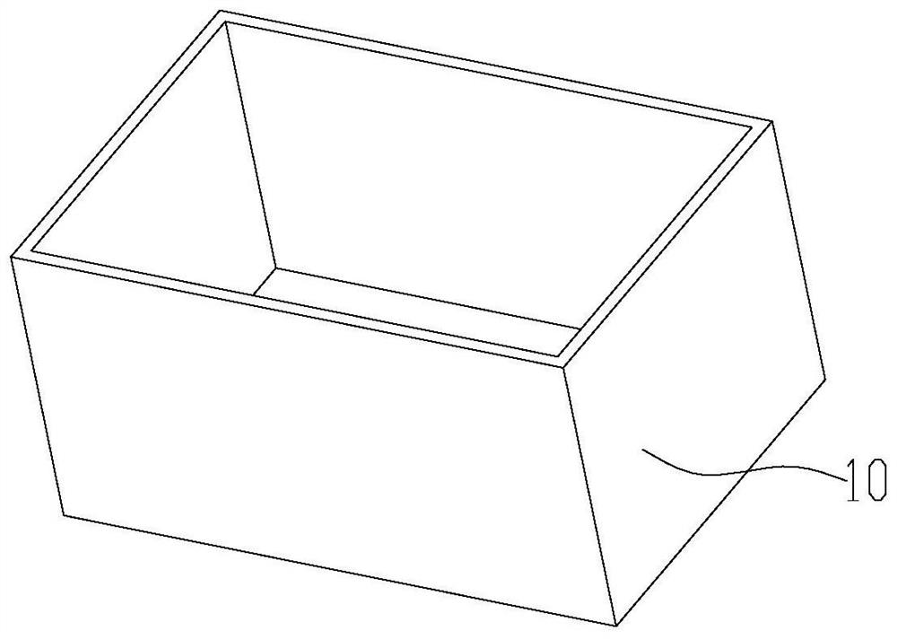
[0039] 1) See attached figure 1 , take the tank body 10, the tank body 10 is a transparent tank body 10, the top of the tank body 10 has an open end, the tank body 10 includes a front plate, a rear plate, a left plate, a right plate and a flat plate, and the flat plate is located at the bottom to form a tank body The bottom wall of 10, the front plate, the right plate, the rear plate and the left plate are connected in sequence to form the peripheral wall of the tank body 10, and the entire tank body 10 is a structure with a cavity inside;

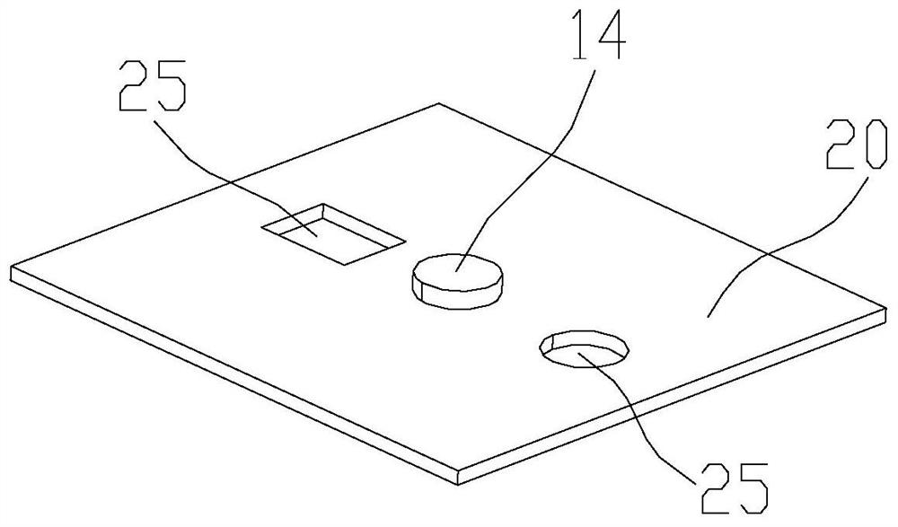
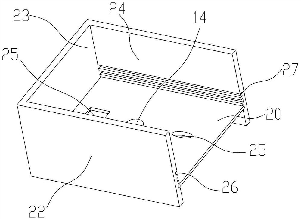
[0040] 2) See attached figure 2 , take the bottom plate 20, open three through holes 25 on the bottom plate 20, among the three through holes 25, one through hole 25 is rectangular, and the other two through holes 25 are circular; the working electrode 14 is installed on the bottom plate 20 in the middle through hole 25;...

Embodiment 2

[0058] In this embodiment, on the basis of the first embodiment, step 8) is adjusted, and the vertical adjustment handle is rotated in the opposite direction, so that the vertical sliding block 41 slides upward along the surface of the vertical sliding rail 42, so that the vertical sliding block 41 passes through The folded plate 36 on the cover plate seat 31 moves upward along the vertical direction with the cover plate seat 31 and the cover plate 30 on it. The sliding column 53 on the horizontal moving mechanism 50 moves upward, and the upward displacement of the cover plate 30 is read as 50 μm through the vertical scale line on the vertical adjustment rod and the vertical alignment line on the vertical adjustment handle, that is, the cover plate 30 and the upper surface of the working electrode 14 form the corrosion gap with a width of 50 μm, denoted as H1; start the electrochemical workstation, observe and record the experimental data, and obtain the experimental result.

...

Embodiment 3

[0061] In this embodiment, on the basis of the second embodiment, step 8) is continued to be adjusted, and the vertical adjustment handle is rotated in the opposite direction, so that the vertical slider 41 slides upward along the surface of the vertical slide rail 42, so that the vertical slider 41 moves upward along the vertical direction with the cover plate seat 31 and the cover plate 30 on it through the folding plate 36 on the cover plate seat 31. At the same time, the connecting ring 55 on the right connecting piece of the cover plate 30 is also Move upward along the sliding column 53 on the horizontal moving mechanism 50, and read the upward displacement of the cover plate 30 as 100 μm through the vertical scale line on the vertical adjustment rod and the vertical alignment line on the vertical adjustment handle, that is, The width of the corrosion gap formed on the upper surface of the cover plate 30 and the working electrode 14 is 100 μm, denoted as H2; start the elec...


PUM


Abstract

The invention provides an in-situ monitoring method for crevice corrosion. The method comprises the following steps of: 1) taking a tank body; (2) taking a bottom plate, installing a working electrode, detachably connecting the bottom plate to a bottom plate base, and horizontally placing the bottom plate in the tank body; 3) taking a cover plate, installing a micro pH electrode, connecting one side of the cover plate with a vertical moving mechanism, and connecting the other side of the cover plate with a horizontal moving mechanism, making the cover plate arranged above the bottom plate andparallel to the bottom plate; adjusting the vertical displacement of the cover plate, and adjusting the horizontal displacement of the cover plate; 4) injecting an electrolyte, suspending a referenceelectrode and a counter electrode, and connecting an electrochemical workstation; 5) hanging a constant-temperature heater and adjusting experiment temperature, (6) adjusting the vertical displacementand/or the horizontal displacement of the cover plate and/or the temperature of the constant-temperature heater again and/or replacing the bottom plate and/or replacing the working electrode on the bottom plate; and (7) repeating the step (6) multiple times to obtain an experiment result. The method is simple, convenient to operate, accurate and reliable in result and high in guidance.

Description

technical field [0001] The invention relates to the technical field of metal material corrosion, in particular to an in-situ monitoring method for crevice corrosion. Background technique [0002] Metal structural parts and metal equipment are usually made of metal materials, such as stainless steel, etc. During the manufacturing process of such metal structural parts and metal equipment, there will inevitably be some connectors, which are usually flanges Or riveting, etc.; in addition, some metal structures and metal equipment also have coating materials on the surface, which will lead to the appearance of gaps. When the metal structural parts and metal equipment of this structure serve in a corrosive environment, there is a risk of crevice corrosion. It is important that this corrosion is relatively hidden, and the corrosion rate is relatively fast. Metal equipment causes serious corrosion and is very harmful. [0003] At present, the test method for crevice corrosion of ...

Claims


Application Information

Patent Timeline
Patent Type & Authority Applications(China)
IPC IPC(8): G01N17/02G01N17/00
CPCG01N17/006G01N17/02
Inventor 徐玮辰邓羽张杰李言涛杨黎晖孙丛涛麻福斌
Owner INST OF OCEANOLOGY - CHINESE ACAD OF SCI
Why Eureka
Try Eureka